
Adaptive USB and asynchronous USB
Binary word and bit depth
Bit perfect
Brickwall filter
Clock
DAC
Delta/sigma DAC
Digital audio
Dither
File compression
I/V (current-to-voltage) converter
Jitter
Non-oversampling DAC
Oversampling
Sampling frequency
Upsampling
Zero order hold
Adaptive USB and asynchronous USB
USB interface normally doesn’t embed the clock, and transfers only data. However, devices that operate in real time, such as D/A converters, do need a clock. Classic USB audio decoders work in the adaptive mode, often employing specially developed PLL to lock to 1 kHz USB data packets frequency coming from a PC, and to generate a sampling clock. On the other side, the latest advanced USB DACs utilize the bi-directionality of the USB interface to operate asynchronously, and work as master mode devices that control the data flow from the PC. This way, a master clock is located inside the DAC, thus eliminating the jitter associated with the PC and interface. (see also: clock, jitter)
Digital audio uses a binary system (zeroes or ones) to represent the specific amplitude of the signal at a given moment. Classic CD format uses 16 bits to represent 65,536 (216) different levels, and 24 bit systems can represent 16,777,216 (224) different levels. A number of available bits defines resolution in the amplitude domain by determining (1) maximum dynamics (every bit brings 6 dB), and (2) quantization error, which occurs because any arbitrary level must be rounded to the one of available levels (this error is shown by this graph’s black curve). This error is also known as quantization noise, though it more resembles distortion than noise in a traditional sense, because it is not idle noise but an entirely signal related artifact. Quantization error increases as the signal level decreases, because at lower levels a lower number of bits is available. (see also: dither)
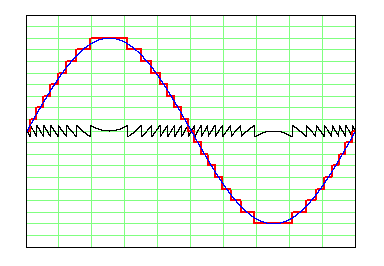 this graph’s black curve
Bit perfect, or bit transparent, is a data reading or transmission system that preserves original data in an unaltered state, with no changes of any kind, be they errors or intentional data processing. In fact, with today’s technology, reading and transmitting signals with no errors is a regular and mostly trivial task, but many devices often intentionally process original data for different purposes, such as re-sampling, level control, mixing, tone control, etc. In a quality home audio playback system, it is usually recommended to ensure a bit perfect path, and such processing is considered best avoided for its adverse effects.
Please note that the quality of digital readers and transmissions is not necessarily fully described by the bits alone, so bit perfect source doesn’t necessarily mean that it is perfect as such – the other phenomenons associated with digital readers, and which belong to the signal integrity area, such as jitter or noise, also count, since they can, and usually do influence the operation of the rest of the audio chain.
Commonly required by Shannon-Nyquist’s theorem, as S-N proposes the system that conveys exclusively the signals inside the passband, disregarding those outside of it. A sampled signal hence needs a steep (brickwall) filter, or two issues appear: (1) aliasing during the recording (A/D) process – ultrasonic content folds down into the audio band, and (2) imaging during playback (D/A) process – audio content replicates itself above the audio band thus producing ultrasonic artifacts. Today, a brickwall filtering is practically exclusively performed in the digital domain, and modern digital filters can be very effective in this regard, with a very steep curve and more than 100 dB attenuation.
Brickwall filters’ transient response is however debatable. Today ubiquitous linear phase digital FIR (Finite Impulse Response) filters suffer from both pre- and post-ringing known as the Gibbs phenomenon, while traditional analog filters, as well as their modern digital equivalent IIR (Infinite Impulse Response) filters, suffer from post-ringing only but have non-linear phase. Sometimes are hence used more soft filter slopes, which trade attenuation for better impulse response. (see also: non-oversampling dac, oversampling, upsampling, zero order hold)
Digital equipment normally needs some clock(s) to operate. A clock that ultimately matters in high quality audio is a “sampling clock”, which is the one that A/D or D/A converters use to convert i.e. “to sample” their input or output signal.
For basic operation, converter chips normally require a bit clock – which tells the converter the moments the bits arrive at their data input, and a word clock – which tells the converter the moments the binary words start or stop. In addition, oversampling filter chips, as well as converter chips incorporating oversampling filters, also require a higher frequency, which is normally a master clock (“system clock”). There is no general rule about the clock that is actually used for conversion – it can be either a word clock (early chips) or bit clock (some multibit Philips and BB) or master clock (delta/sigma converters with oversampling).
Traditionally, a master clock is the highest frequency needed in a given device, and is used to generate the other (lower) clock frequencies. Master devices, such as standalone CD players or asynchronous USB DACs, can derive a sampling clock directly from their local master crystal oscillator. On the other hand, slave audio devices (such as S/PDIF DACs) and multimedia devices that require plenty of different frequencies to operate (as audio/video or network players) use a PLL to lock onto an external source, or to some arbitrary frequency. Normally, it is advantageous if devices can use a crystal oscillator and not a PLL, though the latest generations of PLLs also have excellent jitter performance. (see also: jitter)
As implied by its name, a digital-to-analog converter or DAC is a device that converts digital data to an analog signal, whether current or voltage. Every digital player requires digital-to-along conversion, however DAC can be also a dedicated standalone device. On the other side, the digital recording process requires an A/D converter, which converts the analog signal into a string of numbers.
Traditionally, converters were ladder type (also known as “R2R”, even though the real R2R topology was abandoned quite early), assigning with every bit a twice higher output current than with the previous one. Such a conversion sets high demands regarding the preciseness and stability of the resistors or current sources, and recent converters usually employ delta/sigma processing instead. (see also: delta/sigma dac)
Converter type which decreases bit depth by increasing sampling rate, that way producing a PWM/PDM output which preserves original PCM signal resolution and makes actual conversion (often 1-bit only) trivial or cheap. Due to lower production prices, such converters mostly rule the semiconductors market since the early 90s, now practically completely removing classic multibit converters out of production. Early delta/sigma converters were all 1-bit (“Bitstream”, “MASH”), whereas today’s top delta/sigma chips employ 5- or 6-bit output, to overcome low-bit converters problems with modulation noise, and to alleviate their higher susceptibility to jitter. (see also: dac)
The audio system which stores the original signal in the form of numerical data that represent the signal at given moments.
Commonly, the signal is sampled at equal time intervals and represented by 16 to 24-bit long binary words. Such a principle is called Pulse-Code Modulation (PCM) and is used by CD, DVD, and Blu-ray. As opposed to this, if a sufficiently high sampling rate is applied, a signal can be represented by one bit only, and thus become a digital equivalent of Pulse Density Modulation (PDM). Such a principle is called Direct Stream Digital (DSD) and is used by SACD.
A technique used to increase amplitude domain performance with the available number of bits, by adding the noise that randomizes quantization error during recording (A/D), or the bit depth reduction process. By use of dither, a system lowers the signal-related, ear-displeasing quantization error, and it is able even to record signal levels residing below the nominal dynamic potential of the non-dithered system. On the other hand, the noise added by dither is supposedly sonically benign, because of its unrelated, wideband content. In this regard, different dithering and noise-shaping algorithms were developed.
You can hear the effects of dither by listening to the next two samples. One is “normal” non-dithered sinewave (0.7% total harmonic distortion and 1.5% noise), and another one is dithered, including noise shaping that follows the Fletcher-Munson curve (THD gets lowered to 0.01%, while noise level increases to 4%). For better audibility, a 16-bit system is used to capture a -60 dB signal, where practically only 6 bits are available, and then the level is increased to 0 dB for more convenient listening.
Normal (non dithered) sinewave:
Dithered sinewave:
Frequency analysis graphs for these two files are here (non-dithered) and here (dithered sinewave). Ideally, we would like to have only a 1 kHz carrier, however due to quantization error, many artifacts appear (first graph). By use of dither, such discrete artifacts can disappear and turn into wideband noise, as shown by the other graph.
 here (non-dithered)
 here (dithered sinewave)
A technique that makes the original file smaller in size, so it takes less space on storage media, and shorter transferring time. There are lossless compression formats such as FLAC, APE and AIFF, and lossy compression formats such as MP3 and WMA. Lossless compression makes it possible to fully recover (decompress) original file content, while on the other side lossy compression trades between size and quality, and can not recover the original file with no losses. The compression ratio depends on the technique used. For example, lossless FLAC may save up to 50% of space, whereas omnipresent lossy MP3 may have very high compression ratios, between 4.4:1 and 44:1. For the record, however, please note that the MP3 can not compress CD format for more than about 7:1 (192 kb/s) yet preserving full 20 Hz – 20 kHz audio bandwidth.
I/V (current-to-voltage) converter
All the classic multibit D/A converter chips have a current output, because of their output stage which is a ladder of resistors, or string of current sources placed in parallel (each of them being triggered by a particular bit). However, most electronic equipment and circuits are intended to operate with voltage and not with current signal, and hence this current output signal necessitates a transition from the current to the voltage domain. Essentially, I/V conversion itself is always performed by a resistor and according to Ohm’s law, but there are still important differences with regard to the circuit used, and the way the I/V resistor actually acts. Thus, there is an “op-amp I/V”, but also a “current conveyor transimpedance I/V”, and sometimes all can be done simply as a “purely passive resistor I/V” that is placed directly to the DAC chip output.
One-bit delta/sigma converters change this situation, as their output is a single source that can operate in the voltage domain, and hence does not require any external I/V converter.
Delta/sigma converters with 4-, 5- or 6-bit output can be either current or voltage output, and hence may and may not require I/V conversion.
Short-term uncertainty in the frequency of the clock used for A/D or D/A conversion. It can be also interpreted as “phase noise”, and represented by its own frequency analysis (phase noise graph).
Ideally, converters are supposed to convert (“to sample”) at equal time periods. If there is uncertainty in conversion timing, a sort of conversion error appears. This error manifests as a frequency modulation of the converted signal, making the original signal frequency modulated by this clock’s phase noise.
A cause of jitter is the noise that breaks through to the clock, either via supply, or by different kinds of interferences, but can be also caused by intrinsic parts noise or by circuit shortcomings.
Please note that the jitter, or short-time uncertainty, has nothing to do with and is not in any way associated with the clock’s absolute frequency tolerance, normally given in ppm (parts-per-million). Absolute frequency tolerance influences absolute pitch, but is normally out of the question for regular audio purposes, as it never gets worse than 100 ppm (0.01%) for any conventional crystal. (see also: clock)
Literally, a converter that doesn’t employ digital oversampling. Colloquially it however doesn’t denote early 80s CD players and their converters which performed all the filtering in the analog domain, but a later approach to conversion that abandons not only digital oversampling (and upsampling) but also any sharp analog filtering. This approach, regardless of Shannon-Nyquist’s proposal, denies the practical necessity for brickwall filtering, which is hence of no use and best avoided. Also known as the “filterless DAC concept”, it was originally advocated by Ryohei Kusunoki in his articles published in Japanese MJ Magazine in 1996/1997. (see also: oversampling, upsampling)
A.k.a. interpolation, is a technique that creates new digital samples by interpolating existing ones. So, four times oversampling adds three new samples between two existing ones, and this way shifts the nominal sampling frequency from 44.1 kHz to 176.4 kHz. Such a new signal can not and does not produce useful musical information, but it does relieve requirements for analog filtering (which in this case should be called post-filtering), as a higher sampling frequency leaves a bigger margin for filtering. That way oversampling effectively performs low pass filtering in the digital domain. Oversampling can employ different interpolation algorithms, with different low passing slopes. (see also: brickwall filter,non-oversampling dac, upsampling)
Every digital system implies sampling, because a continuous analog signal must be converted into the finite number of samples that represent it in the digital domain. Classic CD format relies on the Shannon-Nyquist theorem, which claims perfect reconstruction of band-limited signals when the sampling frequency is greater than twice the maximum frequency of a sampled signal. Since human hearing is limited to 20 kHz, the CD sampling frequency was set to 44.1 kHz as sufficient for audio reproduction.
However, the use of the Shannon-Nyquist theorem in the audio is disputed for problems associated with the brickwall band limiting, and for difficulties in representing transient events by the finite number of sinewaves. Consequently, the benefits of lately developed hi-res formats (usually with 96 kHz and 192 kHz sampling frequencies) are often explained by improvements in time domain transient response, rather than by a bare increase in frequency response. (see also: brickwall filter)
A.k.a. asynchronous sampling rate conversion, is a form of oversampling, where conversion between arbitrary sampling frequencies is performed. Hence upsampling converts for example from 44.1 kHz to 192 kHz. Such a conversion is usually required in the mixing process where different sampling frequency sources must be summed into one output signal. In addition, upsampling is sometimes also used in solely playback systems, instead of classic oversampling. The reason why upsampling is sometimes considered advantageous for playback is data buffering, required by this essentially resampling process. This data buffering in itself can suppress incoming jitter, to an extent associated with the buffer length. The price is however that, the outgoing data will inevitably include the effects of all the unsuppressed jitter, and this is why is upsampling, from a purist point of view, often considered only a band-aid. (see also: non-oversampling dac, oversampling)
D/A converter chips create the waveform out of discrete samples by holding the previous sample value until the next sample arrives, and then momentarily jumping to that new sample value. This principle, which produces the famous “staircase” waveform, is named a zero order hold.
Since the shape of the waveform also determines its frequency content, such “stairs” attach the string of the images above the audio band, to every carrier frequency, and are hence traditionally considered to require low pass filtering.
Apart from zero order hold, there is also first order hold, which generates waveform by connecting the samples (“dots”) directly by the straight line, as well as a second order hold, which uses parabolas. Such waveforms are obviously “filtered” in comparison to the waveform generated by zero-order hold, but it is however considered impractical to produce these by the D/A conversion process itself. (see also: brickwall filter, non-oversampling dac, oversampling)
Copyright © 2012 Audial