

AYA release scheduled for this year is coming. We will call it the AYA 4, and a number increment came from its completely changed USB stage, which is now a no-compromise, asynchronous USB, a 192 kHz (with 11.2896 / 12.288 MHz clocks) or 384 kHz (22.5792 / 24.576 MHz clocks) capable.
As such, the AYA 4 is a stereo DAC, based on the TDA1541A, but its USB input stage can be made as four channel interface too, and in this case two channels D/A conversion is performed by on-board D/A stage, whereas two more channels are forwarded as digital output to U.FL connectors, for D/A conversion by another board or unit.
Yet, as opposed to the USB stage, which is completely changed and now all SMT, the AYA 4 will keep the same D/A and output stage of the AYA II, so they remain DIY friendly, and a DIY manual for these parts will be provided to the customers. The S/PDIF stage will be slightly revised, and it will have a bit more SMT parts than AYA II had, but anyone able to put together the S/PDIF stage of AYA II will be able to do it with AYA 4 as well.
AYA 4 transformer will be also slightly different from than AYA II transformer, since AYA 4 requires one additional 8 VAC secondary winding.
AYA 4 board size will be somewhat increased too, and at the current state of the design, its dimensions are 180 mm (w) x 160 mm (d).
And, just like AYA II 2014 and DS, the AYA 4 will be also produced in a limited series.

Ordering
The AYA 4 was produced in two limited series in 2018 and 2019, which are both sold out.
Related topics:
AYA 5
Another story about TDA1541A: 384 kHz
OPA861 output stage for AYA II
AYA II DS, DIY edition
AYA II 2014 DIY edition talks
Hi. If I ordered the module USB input only, do i get the pcb with the rest of the dac as well?
I still have my previous AYA-II DIY DAC transformer, can I still use it if I simply add an other small 8vac secondary transformer?
Thanks
SB
Hello Sylvain,
Sure, all modules use the same AYA 4 board, and difference between them is in pre-fitted parts they include.
So the “module with USB input stage” includes pre-fitted USB stage, and you can normally populate the rest of the board by yourself.
And yes, you can use separate transformer for additional secondary voltage.
Regards
Great, I’m hooked again, I’ll press the order button in a few 😉
Thanks for this great opportunity, SB
Payment done. thanks
SB
Confirmed. Thank you, too.
I’m guessing I’ll receive the documentation by private email once available?
SB
Manual will be either sent by email, or available for download, along with Windows driver, which is executable, and hence usually refused by many email servers. But you will be notified by email for sure.
Regards
Good morning Pedja, would you mind trying to talk a bit about the effect of the isolation transformer. Mostly I am interested in the sonic difference.
Thanks
Ernst
Good morning, Ernst.
This is still somewhat controversial topic in audio. Some swear to hear no difference, and some claim the isolation transformers steal dynamics, “even if they use highly oversized unit”.
The difference is in details (or if they do matter then they are not details?), and results depend on the actual environment (mains voltage, the rest of the system), and how the transformer is done (actual unit, physical set-up etc.). You can consider an isolation transformer as any other (mains) filter, and expect the same or similar effects, but you should be careful with transformer external dissipation too, especially with EI unit.
When working with supply filtering, I always pay attention to the dynamics, background, and tone (pitch, color).
As you might know, I still use the isolation transformer in Audial S DACs. It is made in a way it makes no harm, while benefits may differ in different system and places.
HTH.
Hello,
I’d like to ask about some details of the usb stage.
Is the usb stage kind of implementation of XMOS/Amanero modules ? – so there are some custom made BGA chips that couldn’t be mounted in future? If not, could be even a simple partial schematic screenshot provided later for those who have access to SMT assembly workspace?
Is the data to simultaneus data mode conversion possible only in the USB stage or is done later, so connecting external I2S signal, or by the SPDIF can also feed the DAC with the simultaneus data?
Is the USB receiver stage designed like a separate module, that could be for instance disconnected and used in a different DAC project?
And lastly, what are the demands for the wattage/amps for the lines of the trasformer; is for example 1 Watt for each enough?
Thank you very much for explanations in advance 🙂
Greets
Bartek
Hi Pedga,
Can AYA 4 transformer be used with AYA II 2014/DS boards?
thanks
@ Bartek,
AYA 4 is one PCB device.
There are several reasons why USB stage is not intended for DIY, and hand-soldering difficulty, as serious as it is, is actually only one of them.
USB stage decoder is programmed to output simultaneous data protocol (but it can output I2S too, on request), while S/PDIF uses off-the-shelf receiver, with I2S output. U.FL I2S/PCM input carries the signal directly, as is, to TDA1541A.
There is no reason you can not use AYA 4 USB stage with other D/A unit.
A current required by all lines is up to 60 mA, apart from 8 VAC, which takes up to 120 mA. In my view, a 0.5 A and 0.8 A (respectively) capable secondary windings are fine.
@ Boris,
Yes, it can. It has one secondary winding more, but it is no problem to leave it floating.
Regards
Hello Pedja,
This is really neat.. I’m curious on how you switch from USB input (simultaneous data mode) to SPDIF without using a dipswitch near the TDA1541A.. Thanks!
Frederick
Thanks, Frederick.
AYA 4 has one more relay than AYA II, to switch between two modes. But DIP switch footprint is still there too.
Regards
Thanks Pedja..
It’s cools thst you have a found a way in switching between input sources with no or minimal compromise in performance.
Hello Frederick,
Basically, the choice here is between relays and logic circuits. They both have their own advantages and shortcomings, and in this case I found relays more practical. On the other side, to switch between two clocks in the USB stage I am using the multiplexer.
Regarding TDA1541A mode selection, the same approach was used in the Model S Mk3. It takes a few centimeters of traces to get that mode selection relay connected (or that’s what I managed to do, among the other stuff there), but there is no compromise in this, not the sonical one I can hear.
So, in the AYA 4, the TDA1541(A) mode can be set either by the wire jumper, the PCB DIP switch, or by the relay. Also, AYA 4 will be able to accept either protocol at either U.FL input (AYA II could accept I2S also at either U.FL input, but only the first set of U.FL could accept simultaneous data protocol).
Regards
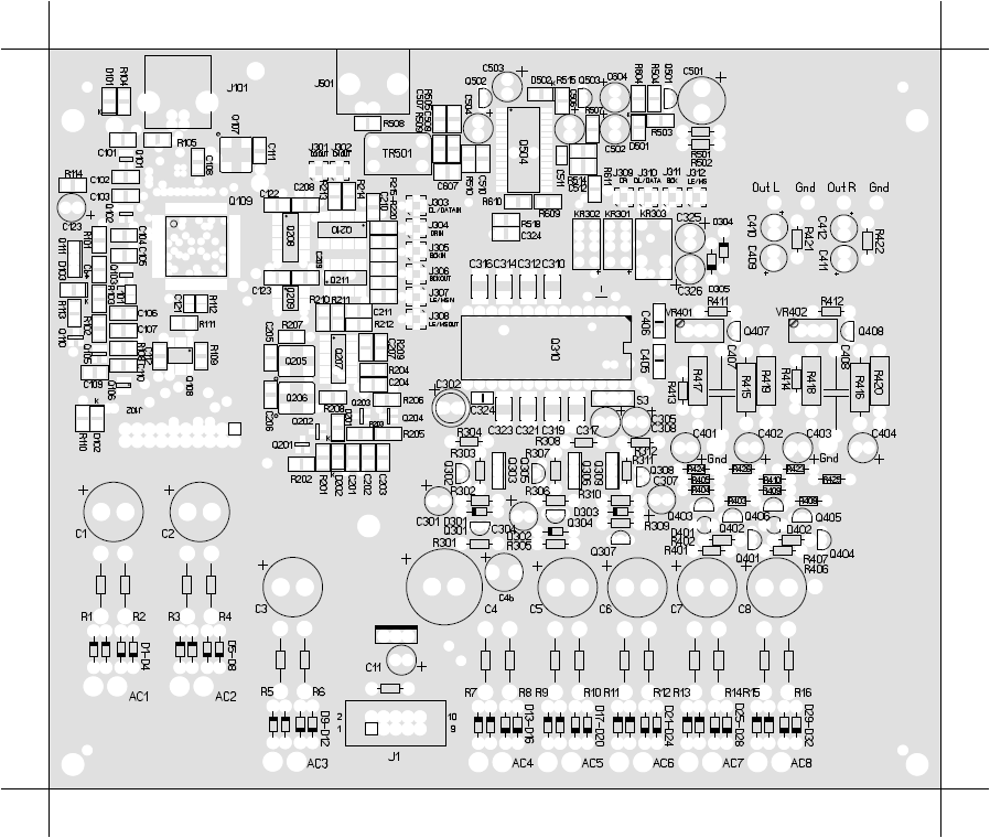
And here is how AYA 4 PCB looks alike.
Ultimately it is 187 mm (w) x 155 mm (d), so the area roughly 30% bigger than AYA II. At left, you might notice the USB stage very similar to Audial USB interface board, and at right something very similar to AYA II D/A and output sections, with S/PDIF stage now above (or behind). In a nutshell, that is what AYA 4 is, but some features make it still more than the plain sum of these two.
(Click on the picture to enlarge.)
can I order the aya 4 with pcm/i2s input and spdif input?
I mean can I order the compete AYA 4 with SPDIF and PCM/I2S input with chassis
Thanks
Reply sent by email.
Regards
Are orders still open for this?
Andrew,
Online ordering is not possible anymore, and the manufacturing process is underway. There will be however still some spare samples, and at this time it is best to send your request by contact form.
Regards
Dear Pedja,
If using two transformers to provide power to analog and digital parts individually, will improve sound quality from AYA4?
Thanks
Hi, when the pcb is expected to ship to us? Thanks
SB
@ Arthur:
Speaking at most practical level, I must admit that I’ve never tried this particular option with AYA II, III or 4, however I wouldn’t expect any improvement. I was however playing with different transformers setups before, and I found myself preferring to have all the necessary windings at one transformer, whenever possible.
Also, please note that some circuits in this DAC are purely analog (output stage), some are mostly digital (USB and S/PDIF), and some are real mixed signal (D/A part). “Mostly” means that you can consider the clock at USB, and PLL at S/PDIF stage rather analog than digital in nature, even though they operate high frequencies, so it is not always easy to make a clear distinction between the analog and digital side.
@ Sylvain, and everybody:
Yesterday I’ve sent an email with this information, so please check your inbox(es) or spam folder(s), in case you missed it.
We are just starting to ship, and the orders without USB stage will be probably all shipped this week, while the orders that include USB stage will probably start shipping next week.
Regards
Hi, Pedja
A couple of questions that came to my mid, reading the AYA4 assembly manual:
1. Will be possible in the future to replace the master clock (by ourselves) to the 2x higher/lower rate clock (resoldering the clock with some selection in the firmware drivers)? – I’d like to try listening upsampled to 384kHz – but maybe I will end up with listening no-over/upsampled 44.1, or maybe upsampled 192kHz with slower clock will turn out to be optimal..
2. Would be possible in the future to switch the USB module output to I2S or PCM mode output for usage with other Dacs?
3. Shouldnt we select by even some jumper the frequency division rate, so that for both USB – 32bit frame and SPDIF-64 bit frame, we would still preserve the 4xFs DEM clock? Is intentional to clock the DEM with 88.2 khz with simultaneus mode? (As I remember from the TDA detailed documentation, the 4xFs, i.e. 176.4 was optimal, the deterioration of the signal started very slowly to rise above this frequency.., but it the other hand we’d like to have the dem clock as fast as possible to improve DEM cycle averaging accuracy, so also not lower than 4xFs)
4. Do you have any opinion of using higher capacitance DEM decoupling capacitors (preserving their same high quality, even to uFarads, eg 4.7uF)? Or all 100nF are optimal by your experience?
5. What do you think about employing additional so-called level matching of the i2s lines (operating with switching levels very close around the input L/H threshold), to reduce the switching noise, and even filtering by small cap to gnd?
6. What do you think about driving the DEM differentially (both COSC pins, symetrically with Q and nQ) for example with the divided clock passed through some DFF clocked with the master clock?
Greets
Hello Bartek,
1. Yes, it would be possible.
2. This would be possible too, however the AYA 4 USB input stage was meant exactly like that, i.e. as an input stage for AYA 4, even though it has additional optional feature to send two more channels out to the other D/A board. However it was not meant to serve as a standalone USB interface.
3. TDA1541A THD+N performance slightly decreases as DEM frequency goes above 250 kHz, but it is not that huge, as you can see from the attached picture, originating from the old Philips papers.
On the other hand, I found no problems with low DEM frequency, down to 80 kHz. Having said this, and having to take the BCK (and not master clock) as a basis for DEM clock, I settled on the scheme you see in the AYA 4 (and AYA II DS), which works with sources between 44.1 kHz and 384 kHz, and quite consistent performance in this regard.
4. My first TDA1541A DACs were using 2.2 uF at two most significant bits, however the gains were not that important, especially taking into account inevitable compromises regarding the caps quality. On the other side, Philips papers recommended completely abandoning DEM caps, if synchronous DEM clocking is used. I did not find it however sounding good, either. So, a 100 nF is where I am at, for many years now.
5. I did not find any use of it, either technically or subjectively speaking.
6. Simple circuit driving only one pin appears to perform the same. The jitter is not critical here.
HTH
Dear Pedja
are there any boards still available ?
best regards
Pepe
Pepe, at this moment there is a couple of spare boards with pre-fitted USB stage, and one more board that will be fully populated.
Also, one information regarding the shipping. All the modules will be shipped until Monday. Then we will start shipping completed devices, and hopefully send them all during the next week.
Thanks everyone for patience.
Regards
Thank you very much for your response Pedja, I have just sent you a message via your contact form asking for pricing on the boards. You will see there my email to answer.
best regards
Pepe
Reply sent.
Regards
Hi all,
I want to share with you my personal thoughts and recommendations about Over/UpSampling and non-OS with the AYA.
To start off, at the very beginning I will say, that with good quality upsampling the AYA with TDA1541 sounds just GREAT and for me is MUCH better than non-OS. With good upsampling all strong points of the sound of the TDA are still there, but the sound additionally opens, gets more evenness and clarity. It just then outperforms such DACs like the modern and praised Chord 2Qute or Audio-Gd DAC19 (on BB PCM1704) that I also have in the clarity, multi-layer space, texture.
For me everything is in the fact that here on AYA-TDA the instruments, voices, have the cleanness and purity of sound, without added such glare/reverb-like effect I observe on other dacs, and that gives the natural, live sound.
As you may know there were always problems with IC oversampling filters that feed the TDA in CD-players, because they added jitter, their quality was also mediocre (with design compromises) and in some (important) aspects it just didnt sound good as clean non-OS.
But now we can high quality upsample on the PC and feed the TDA in low jitter simultaneous mode with the clean signal from asynchronous USB.
Why upsampling is good? Because the aliasing spectrum will be pushed far away from the audible range (important when there is no post filtering), and the sinX/x 3db compression of the highs (20khz) will be also far away and negligible. In that way we also avoid intermodulation distortions and other bad effects – so the audible range should be restored in the way as recorded.
What upsampling I find is quite good enough?
As I prefer to listen in the best possible way I currently can, I (have to) play only from the computer via USB (the Toslink and Coax connections on all dacs I had always sounded inferior – maybe with additional buffering/reclocking interfaces would be comparable, but on non DYI dacs thing is complicated).
If I had a music stored in file I would play from AIMP, which have built-in high quality SoX upsampler, and can play in Exclusive mode through WASAPI Event. But because I dont have much music in files, I play from lossless TIDAL – only the problem is it doesn’t have built-in any upsampler. BUT, I found that the Windows upsampling is for my ears maybe not so good as in AIMP, but quite good enough – ONLY IF we preserve the integral multiplication of the original frequency. So – if the source music is in 44.1 (most of the content) – the upsampling have to be set to for example 176.4. If the source music is in 48, or 96kHz (Tidal MASTER) – you have to switch in the system the upsampling to 192kHz. Without the integral 4x or 8x multiplication, the result is not so good. The only compromise is that the device output cannot be set in exclusive mode if we want to use the Windows upsampling, and is potentially open for windows mixing. But if the default sound system output will be set to any other device (like some integrated soundcard, digital output or something else), there shouldn’t be any added disturbance.
Still I’m looking for a solution for exclusive mode and upsampling (maybe some virtual device then upsampling and routing to the AYA), because the AIMP-SoX upsampling is next step forward, but as I say, for me even in the non-exclusive mode and Windows upsampling is quite good for start with if you listen from TIDAL or Spotify.
I’m happy to hear your experiences.
Thanks Bartek, great and most useful post.
I fully agree that it is way better – both less critical and more practical – to implement an oversampling in PC software, than by hardware. In fact, this probably applies to any sound processing, including sigma/delta D/A conversion.
Personally however I still have to hear an oversampling that is beneficial soundwise. But please note that the different findings here may be associated to the different downstream devices. Some simply do not have problems with images. And I have built my system using non-o/s sources most of the time for many years now.
Anyway, I am always ready to try the things that I did not try before, and make things better. So thanks for pointing out the AIMP/SoX, I will try this one.
Regards
You might be right Pedja, that some systems may be more and some less sensitive to higher spectrum images. I expect that the less sensitive systems are for example that with output transformers (tube amps) that are high frequency filters in their own nature.
When you wrote you will check the Aimp-SoX upsampling I thought I will try again for myself to compare it to the windows upsampling with some limited music I have in files (from cd), as I wrote recently I only listened from Tidal with Windows upsampling and were very satisfied from the results.
Well, really, in our pure data connection via USB to the TDA, the choice of the upsampling algorithm changes a lot, and have to be carefully selected by everyone for own tastes.
The well regarded Sox upsampling sounds smoother, with lower tonal balance to Windows upsampling (which in fact we dont know what algorithm it is exactly, only heard it probably use Pacific Microsonics algorithms that Microsoft acquired some time ago). But Windows u/s have more highs, that in for example orchestral recordings can give in my system spectacular results – giving that more “air” and space with well focused instruments still with natural timbre.
So yes, the preferred results may be veery whole system and tastes dependent, and I would recommend to also give a try to Windows upsampling as it sounds just different. But in any case, personally I would still say that in systems that dont have natural capabilities of the high spectrum suppression, good quality upsampling sounds better :). And definitely doesn’t have many drawbacks of IC oversamplers and asynchronous upsamplers.
And this is great, when we can have impact on the sound obtained, the DAC is doing just its work, and we are not forced to rely only on one dubious quality IC filter.
Pedja, could you reveal, what kind of system, amp/speakers you have?
Also I will be very interested of your observations of the upsampling in your system later.
Greets
Transformers do work as low pass filters, and may help somewhat here. This relation is also not simple, but If you look at the latest Audial S4 DAC graphs, you will notice the IMD is somewhat lower when measured at transformer coupled output, than at conventional capacitors coupled output. FS was 44.1 kHz. Since these transformers are the last parts before the output, basically this means that they help my measurement card.
Generally, I prefer high bandwidth active parts, and low pass filtering done passively. Feeding the active devices with signal slopes above their capabilities may produce problems.
Most shortly, my amp is made of potentiometer (low impedance shunt, or sometimes digital pot), and National (now TI) power opamps, which drive the pair of Quad electrostatics.
Regards
Thats very interesting topic too, Pedja.
I only want to add one notice, for those who want to try the upsampling in AIMP. There is also a dithering on/off option on the “transformation options” tab there. That was it what I had unchecked, and that was it what differentiated mostly the result that I got from Windows upsampling. So apparently the Windows upsampling do also the dithering.
With the dithering on in AIMP, the results are now I would say from the same family.
For me, dithering (when done properly) opens the sound even more, giving more space, what is especially noticable in large orchestra recordings, with the instruments spread wider and deeper.
There is a one detail to take care with all the upsampling/dithering/noise shaping: the output bit depth given to the algorithm generally should match the bit depth of the DAC, to be done in the proper way to get the best results – as this cannot be substituted by just cutting the LSBs, but this is for another discussion..
Bartek,
I checked the AIMP, and I can confirm that it is very interesting piece of software, apparently able to do everything my long term standard Foobar2000 player does. And it needs no plug-ins for ASIO and WASAPI, however it takes some caution in everyday use, since the output format resolution has to be set manually.
As for the oversampling, AIMP is very interesting in this regard too, and highly worth experimenting. Many problems we experienced with oversampling chips simply don’t exist in this implementation, or are moved to the benign zone. As for its possibly still bad sides, it apparently manipulates the instruments scales and positioning, and it can soften the attack. It is a bit tricky area, so for now I will remain careful with conclusions.
Regards
Regarding the foobar2000 – there is also possible to download an individual sox-based plugin for it – that can be customized more than in the AIMP. I find that standard Sox presets are too strict and in practice dont give the best sound that can be achieved – which can result for example in some soften of the attack, as Pedja said.
I find that enabling some aliasing – gentle filter transition band and lower attenuation of the rejection band gives a possibility to connect benefits of both NON-OS and OS. Also the more gentle the filter, the less ringing we have in time-impulse response.
For the tweaking, for Foobar I recommend the Resampler-V DSP plugin which integrates both Sox and SSRC upsamplers (you can switch between) and graphically visualizes the current filter settings. What is most important every tweak works instantaneously to the played source (no need to restart etc).
My starting point to recommend are:
upsampler: Sox, filter: linear, transition band: 93%-107.6%, attenuation e.g. 96db, or 110dB.. (really depends on needs, it can give less/more detailed sound, but personally I would rather avoid high attenuation values)
[the 100% of the band is the Nyquist frequency, ie for resampling source of 44.1kHz is precisely 22.05kHz).
The other kind of filter can be selected too, like the mimimal/intermediate phase – and sometimes they could sound better, more precise, but I’m not really sure if that would work equally good for all music material – although they dont have the preringing in the time-impulse response like the linear filter, they frequency response is not linear and it may give some problems in other place..
Anyway, for me that way the upsampling results can be way better, customized to the system, than standard Sox presets which natively AIMP only supports (although I like the AIMP player much more than Foobar). And for those who like experimenting and tweaking I would highly recommend.
Hello Pedja,
I would like to ask if the USB input to AYA4 need the 5V supply from the USB?
If not I would like to try to disconnect the 5V supply from USB and see if it can reduce the influence of DATA transfer inside the USB cable.
Hello Arthur,
AYA 4 does not use USB +5 V supply to feed any circuit. Internally, there is only one, logic connection to it, usually however not needed. So if you disconnect USB + 5 V supply everything should continue to operate properly, but you probably won’t gain much by doing this, either.
Regards
Hi,
I just saw one (220V input) on sale in diyaudio forum. Can the transformer primary be configured to 230V input?
Hi Wil,
So long as it is the transformer supplied by Audial, it will work properly with any voltage between 220 and 240 VAC.
Regards
Thanks Pedja.
Hi Pedja,
I just bought a AYA4 fully built from a forum member.Just wondering where can I download the latest audial USB driver for window 7?
I also like to know if there is any additional instruction manual or schematic diagram that comes along with the fully built unit, in case I like to mod or connect the U.fl to my rpi hat.
Photo of the serial number for your reference.
Hello Wil,
Just log in, please, and refresh this page. You will see the driver and assembly manual in the downloads area.
Regards
Hi Pedja ,
I tried log in and refresh the page, but all i see is the user manual pdf.
Hi Wil,
We made some fixes. Now both your account permissions are fine, and some broken links have been corrected too.
Also, there is one important information regarding this site. We’ve set up a real forum, and instead of this blog interface, we can move all the discussions there. I believe that the forum interface will be more useful, and there you can also start the topics.
https://www.audialonline.com/forum/topic/welcome-note/
Regards
Some thoughts about upsampling:
As all is a trade off it could be interresting to extend the discussion & experiments with the layout around it. I mean the say benefits of the upsampling VS constraints to do it : noisy PC ground, noiser phase noise crystals when going with higher speeds.
A first experiment is to know if our own hifi and ears are able to check difference between x2, x4 or x8 upsampling. And do again this experiment by chosing the max frequencies of the crystals on the clock in order to see how the low frequency crystals could help as well. So: 5.xx M Hz to 24.xx M Hz in simultaneous mode? I assume AYA4 has its USB to simultaneous
mode instead of I2S ?
Some also say reducing the speed of the USB bus to its lower speed (by resistors inputt choice before the cmos chip? or CMOS usb chip programing ?) has some benefit for sound quality playback… but that also means sampling frequency limit (96 K Hz max for instance for the 12 Mb/s full speed mode and maybe even less for the low speed mode at 1.5 Mb/s : 44.1 K Hz sampling rate limited?)… which can permitt to lower the Xtals speed choice as well according to the result of the first experiment.
Upsampling from a powerfull PC has some benefice as said above… but in the same time have a noisy usb outputt (even if battery powered laptop), so maybe breaking the ground loop and its noise with the PC and the usb inputt of the dac board could improve things (or not). For instance to experiment with such chip as the ADUM4160 from TI or octocoupler. While also staying with isolator chips after CMOS processing and before the Xtals as AYA4 layout.
An other option is to use renderer like RasperryPi with noise isolator hat which are more quiet than huge PC. While USB of such renderer is noisy too… just maybe less !
There are some Linux based distros like PicorePlayer or MoOde for instance that can enable or disable SoX upsampling features with the GUI. In the same time I’m not sure one can enter in the filter choice options as decribed in the post above.
I would (only) guess that the oversampling done at PC does increase its noise, but I don’t expect this problem to be any close to the problems brought by the oversampling processor chip sitting just beside the D/A chip.
Still, people dealing with PC subjective sound performance, way more than I do, consider PC noise very tightly (inversely) related to its sound quality.
Yes, the AYA 4 USB stage output is simultaneous data protocol.
Interesting thoughts Eldam! I was supposed to write my impressions about the 352/8x clocks switch, but so many other things and new experiences I came across during this time while doing experiments with the AYA, that still I cannot write any final opinion.
Like for example how things change with good power cables, or even better just powering from batteries – even only powering from batteries just the digital stages – USB, isolator and dem clock.
Also how the “digitally the same” digital signal also influences the analog output (I tried various versions of “i2s attenuators”, “stopped clock” operation etc – making things not always necessarily better).
And for the USB – even we have on the AYA the USB stage isolated, with separate ground – when the laptop is powered from batteries or connected to the AC makes difference, and yes, from batteries is better.
As you say I think the good USB isolation, isolation before the isolated usb stage is needed.
Currently I see the main problem is the faster clock make worse sound with the same sampling rate (for example 176.4). I have on the board both 11/22 Mhz clocks (so only for 44.1 and multiplies) and I switch the multiplexer manually by the jumper – only I have to revert or upgrade the firmware from the pc. So the 8x rate cannot be equally compared. From TDA side, with 4xOS or less, after the reclocking the Latch, clock and data with the oscillator clock the signal should be digitally the same, so we have some issue not addressed (the faster clock have higher noise, or switching noise is polluting the digital signal).
But for me still 4xos (176.4) good quality upsampling sound better than non-OS – it just more opens the sound, also the sound is less “raw”, more relaxed I would say. Yes, there is a difference in the same direction between NOS->2x-4x (but not 8x unfortunately from the reasons above). Now I use Audirvana for both playing from Tidal (it has a native tidal client) and from files. It has built-in sox with possibility to tweak the bandpass, response of the filter etc. And it just handle very well the wasapi/asio usb output.
Also I can say that I use 4x DEM ratio for the 4xOS, so it runs on 705.6 khz (I have also installed microjumpers for the selection on the freq divider output). It just sound better – lower DEM rate for me just sounds muddy. I know the graph from Philips visualising DEMfreq vs Deterioration (also posted by Pedja above) that suggests that higher DEM makes worse, BUT: wasn’t it measured with the DEM generated by the internal oscillator from the on-chip crosstalk? We also know from the same document that “the higher DEM frequency the lower duty cycle accuracy” – But we inject the DEM clock with equally good duty cycle accuracy, not from the crosstalk. And even theoretically – only the switching through all 4 DEM cycles during one single sample period makes the whole DEM system working correctly in time domain.
Eldam your thoughts are right with using the lowest needed clock frequency that is really needed for used sample rate, and for this purpose a low jitter programmable oscillator would be perfect. But we would need support for that from the usb stage.
Also I’m not sure, and I’m going to do some converter prototype on logic gates to check if we really need the 32 bit frame in simultaneous mode. If 16 bit frame with latch going high for the half of the last clock period would not work – like in fact it is shown in the TDA1541A datasheet. Then we wouldnt need to switch to faster clock for 8xOS.
My current test plan is connecting external low jitter programmable clock (from Silabs, SI544) and disabling the onboard clock, also omitting the multiplexer (that is supposed to add its own jitter). Also I’m going to try some more complex voltage regulators like the Super TedyyPardo (but it would need to design pcb so it would take some time) and see if they work similarily well as batteries.
Also I have waiting to try the “famous” PMD200 oversampling filter to test how does it compare with the sox upsampling, and maybe just use it without the PC.
Another interesting experiment is to test on the AYA board another DAC, like AD1865 and see how it sounds in the same environment :).
I also thought about the Raspberry for upsampling :), would have to read about the other possibilities you wrote. But I think, and my goal is that, that right usb separation should be insensitive to the USB source, if it is a ac-powered PC, or battery laptop. There is a USB IPurifier, and probably other products from-the-shelf, but I have no personal experience. Good tip with the ADUM4160, haven’t do a reaserch for IC USB isolators yet.
Hi Bartek,
The USB “purifier” or USB “isolator” are made with such chips + eventually EMI filtering, filters. I didn’t tried it yet.
My experience is USB separation is NEVER insensitive to USB source. Even using a laptop with battery, there are so much smps and noisy regs into the laptop/PC that the USB is noisy, hence all the USB “cleaner” moduls sold here and there…
I use a relavitly complex digital front end made with a Fifo to split the time domains between the USB asynchronous inputt & the dac. The second time domain has its I2S signal resynchronized by a clock in order to reduce the jitter. At least it’s not totally a good solution as all those uf-l cables add length towards the dac chip so jitter (I was the guy who asked Pedja Rogic to add uf-l input plugs when the AYAII 2014 was going to be launched and many thanks for that Pedja 🙂 ). The AYA4 has the best layout solution : unique pcb, ground separation as you said, close crystals, impedance matching of the signal traces… All those good things that are making Audial expertise launching very good products wich sound good.
Anyhow, you can hear the USB source, isolator, FiFo or not ! It’s funny to me that I had to work hard of USB wire selection to acheive a better sound despite I have an ARM NAS with usb outputt for audio streaming which has a low power and simple power scheme (certainly very close but quieter of the today RaspberryPi like renderes). But as I say above, not tried isolator options at the USB inputt of the DAC yet.
The famous upsampling/filter PMD100/200 chips introduce certainly some others problems as an active device- crosstalk noise and so on ?) that is a mess for the clock and latch signals. Pedja Rogic answer just above your post make it very clear.
But that’s my understanding WindowMediaPlayer uses the filter of these 2 upsampling chips as owner of PMD (and maybe WMA compression codec as well… losless while sounding very good as figured out to me Shane C. friend who has an incredible DAC with AYA hearth in it).
Indeed the layout of AYA board is very good, the powersupply stages are fantastic, btw did you try my tip about the -15V rail (ref of caps for C4 & C4a + no lytic cap near the dac chip at C302 but smd decoupling at the bottom of the board : 0.1 to 0.47 according your test… avoiding ceramic caps there is mandatory, at least according my tests&tastes) ? I would like so much having this board for AD1862 or PCM63 dac chips but you must go into a new layout development of the board layout and the DACs from Audial has a sota layout made “sur mesure haute couture” for the TDA1541, especially for 2 layers board which suffice for such dac chips & speed. And my experience is 16 bits is not really a limitation be it linear on all the bits or not, but the care you take of all the environment as we are talking about: yes it’s matter a lot…
Well it’s a good news there is a second run of the AYA4 dac, and my bet is the 192 KHz version should suffice if not better… indeed who has 352 K Hz or more reccordings… so few at Tidal or Qobuz. 99% of the CDs and losless internet platforms are 44.1 K hz. And why bother, even if oversampling at playback can be good (matter of taste imo…) all the today Analog to digital chain during reccording/mixing process is made with 192 KHz or more upsampling that remove greatly the quantification noises or phantom images bellow the Nyquist frequency, say 42,1 K Hz. Ok there is still some trace, hence the upsampling discussion. But my bet once again is todays reccordings are fare better, despite loudness war, and what we hear the most is the mixing of the reccording engineers… not really the sampling rates.
The best news of the day is to be able to get a DAC as the AYA4 : there are no better 1541A DACs made by & for DIY enthusiasts you can see here and there on the diy forums. We should tell that to our audio buddies :)… cause my AYA2 2014 is still beating ESS dacs of today… and with more musicality & versality.
Regards,
Edit: a bit long post, sorry for that.
I too have problem with shortening the posts, when there are so many things to discuss :). Maybe we should move to the forum? I see that several separate topics would be needed for our discussion:
1.- frontend devices, options 2.- upsampling 3.- aya psu mods 4. other dac chips
Actually fitting the stereo AD1865 (even favored by Audionote over the ad1862) to try into this board wouldn’t be so difficult. I’m going to do an adapter (for the smd version of AD1865) to the tda’s dip28 socket for it. Only for the most clean solution the usb stage would need to be programmed to output the data in 2’s complement (inverted msb), in PCM mode in general, so that it would not have to be done on logic gates. So we would have to again ask Pedja for the PCM output firmware. But let’s move to the forum for further discussion about it.
Eldam, could you write more about your digital frontend? So you use it for playing from NAS? I’m very interested in that, because I’m looking for some convenient solution that would not need the PC connected on the other end of the cable, but still having the same quality. – Another good place to open a new thread on the forum about this topic.
I guess the typical integration of the PMD filter could bring other problems, but first thing I want to compare is just purely its oversampling algorithm vs sox in the same environment – that is playing back upsampled file through the usb (previously recorded from the filter through i2s/spdif transmitter). Who knows if windows is really using without any simplifications the same algorithm, and if so, it cannot open the device in exclusive mode..
For my knowledge it doesnt matter what was the frequency/bitdepth of the studio processing for the requirements for the analog reconstrucion process. The quality of the recording will be definitely much better of course, but at the end, when mastering to 44khz, the material has to be band-limited to 22khz and sampled by 44khz. And unfortunately when outputting pure 44khz samples into analog in NOS/Zero-Order-Hold and No-analog-filter, you are still prone to alias images and (worse) audio band intermodulation..
Yes, I tried your tip and I added the 330uf, and it definitely improved much :). Although I finally left the 100u close to the DAC, without the 100nf. I made these experiments some time ago and have to repeat them, as I changed in the meantime many things in whole system, so the conclusions could be different. That time (and I use in this configuration till today) I found together 1500uf and 330uf(/35V) of Panasonic FM better (I tried the 1200 FC). Could you tell Eldam, which exactly nannofarad caps are you using? If not ceramics, the Panasonic films?
Maybe lets move to the forum “Aya psu mods” to summarize the PSU mods. I’m opening the thread there.
For me too the AYA and TDA1541 are still surprising me, even with comparison with more “modern” or “better specification” dacs. Improving something in the audio path and the TDA still have something more to say :). But also still I see it is no last word, there are options to even make it even better. Like powering the digital supplies (with TDA’s +5V) from batteries bring so much more details, there is place to experiment with programmable clock etc. Thanks to the AYA, and Pedja of course :), I learned so much during various experiments and still learning :).
Hi Bartek,
I think you’re right about the need of reconstruction filter aka upsampling at playback (same thing as far I can understand). Because of the trade offs, one may prefer NOS playback. It’s easy with some soft which allow the playback via computer to switch from the NOS to x2,x3,x4 oversampling if the frequencies of the crystals you have allow that.
About the caps : it’s all about your whole hifi and one has to adapt according the final sounding. After hundreds tests, I liked so much this mix of Pan FM (330/35v long length, 5 mm gap legs) & FC (1200/50v short length) than I had to share. But for me leaving the 100 uF is not as good than remove it and putt the close decoupling: caps according your taste and final result: lytics with good inductance (2.5 mm gap between the legs) should be tested as surface mount of all sorts or film caps with radial leads. But and that’s an important point: according to me, my hifi, my tastes: leave the smd decoupling of the TDA -/+ 5V unpopulated : so juste use the smd decoupling of the -15V at the bottom.
The capacitance from my experience is found from 0.1 uF to 0.47 uF. For me this arrengement sounded better than with the 100 uF, be it Black Gate N caps or NX, Oscon, Rubycons and all the dozen brands I tested with several capacitance and voltage (yes different voltage of caps gives different sounding results in the same cap model and notice I gave very precise capacitance, voltage, form factor about the caps I testimonied as a very good departure base for tweaking, at least according to me). One has really to try and experiment to find his sweet spot. And yes, you have to test as well the ceramic decoupling at the smd decoupling area (I tested both X7R and NPO without liking it in the final rendering). I use no DC blocking/High pass filter caps at the outputt but I leave the 150R resitors at the opa861 outputt as I prefered with than without… but a very specific resistor: I give here an important tip I keeped for me and few friends everyone should try now as it gave me important improvment : The Allen Bradley yes… but in 1/4 wattage only (the upper wattages gives total different results and I believe it has to see with the diameter of the leads as I tried also with very thin wires and close gauges, and it’s ok despite the gauge of the pcb trace is bigger after as the wire to the RCAs as well; btw I use silver/copper plain 22/24 awg.). Try to hear triangle and cymballs with this 1/4 w AB resistor and please give a testimonial after ;). Now I don’t say it’s universal : one has to start from the offical BOM first, let burn in the whole DAC one month or two, then adapt if wanting.
I agree, too much subjects here, let’s move on the forum area.
About battery powersupply… Indeed there should be something to test with the modern batteries made from LiFePo4 (A123 brand being the best from the testimonials of some hifi forums): because the impedance is super low. But many trade offs here : reg chips after (LT3042, etc) is wasting the advantages according my tests (tried on my clock board made of Crystek CCHD-957 crystals) as the caps too. So not easy as these cells are 3.3V and multiple in serie (6.6V, 9.8V, etc). For me, caps has the advantage to tailor the sound and regs discret typology of the AYA is a sota one imo.
I created a topic on the forum “AYA PSU MODS” where we can switch part of the discussion about the psu caps/psu in general.
I pasted there part of your answer, so everyone could find it in one place. Could you continue there? So you even recommend hundred-nannofarrad electrolites to use on the decoupling place instead of smd ceramics? – do you have some favourites?
I use no dc-blocking caps too. Currently I have all Vishay-Dale CMF resistors in the output stage area, but I have on the shelf waiting the AlleyBradley and PRP resistors to try (good tip with the 1/4W, as I have purchased only 1/2W where the layout size allowed).
But with the resistors tests I’m waiting for the end (and still can’t wait for that) – as I’m not pretty sure if such vintage carbon-composite resistors like the AB are not coloring in some way – maybe very good way – but I want to be sure I’m trying to stay neutral till the last step.
Regarding the batteries I used NiMh packets (7 cells each) for the USB, isolator, DEM and Tda +5V. Nominally it is 8.4V, but when charged it is about 9V. I connect them directly to the original AYA regulator input – just to the capacitor legs, after the bridge and stopping resistors (so the resistors and bridge are floating). For me there is great difference in detail.
For which part and function are using your “clock board”?
PS: Also, as an “upsampling advocate” 🙂 I’m going to start a topic on the forum with a summary of my upsampling recommendations so that they wont be lost and for the continuation of the discussion.
About the analog reconstruction filter: theoretically an ideal filter should perform not 4x not 8x but infinitely-x with infinitely resolution “oversampling” in analog domain.
The higher and longer is the stair step (so the lower the samplerate) the harder is to design such filter and if there is no any – the stronger the aliases and intermodulations with the audioband.
Up/Oversampling generates in digital domain additional (more or less accurate, depending on the algorithm) inter-samples, so that the stair-steps are smaller and the waveform have in the time-domain higher resolution. But still in fact what we ideally would like to have (and which was in reality the original analog waveform after the bandlimiting) a continuous smooth waveform without any steps (as they definitely weren’t originally there).
I guess that high quality upsampling connected with high quality, properly designed, discrete component analog filter would be the best combo.
@Bartek,
I know Vishay-Dale are liked, but I find the CMF55 always bad each time I tried it !!! It is on my passive parst list in the area “garbadge”.
AB 1/2 W is good, but please try AB 1/4 W for the protection resistor at the outputt of the buffer. you can make a test without soldering it… then trying the 1/2 W: it’s a good devil in the details lesson! I would be happy to know the gauge size of the AB 1/4W leads ! You can also try with a 32 to 28 AWG wire.
Avoid soldering with Ag mix solder please. Notice the gauge size of the wire for the DC caps bypass (in case DC caps are removed as the 100k shunt resitors) change the result: a good equilibrium in my hifi was 24/22 awg one core wire till the RCA plugs.
That is interesting.. Good to know the CMFs could not always be a good choice – I’m going to also upgrade some resistors in my amp, so maybe I will order PRPs then..
You are so tempting to try the ABs, so maybe really I will try them this week, even temporarily. But I have to order the 1/4W version.. Interesting your findings even about the wire bypass. I have installed there standard 0.8mm (20 awg?) silvered copper solid wire (just the typical silver wire from the spool for electronic work). And I’m soldering the typical SnPb – didn’t know it could also make difference.
BTW, also by your recommendation I use the FSCEX 1n polystyrene cap, but I dont know if you know its proper polarity: the blue marked side is the outer, say “screen”, side of the capacitor, so should be on the gnd side.
One of my interesting findings was that AYA with my amp works better with higher capacitance interconnect. I have made two – one 0.5m, second 1.5m from the same coaxial (shielded) cable, with the same connectors. So probably the additional capacitance makes some good filtering, and smooths the output stair-steps. On the other hand the shorter cable works better on my other filtered output, sigma-delta dac – so in that case would confirm the rule, the shorter the better, but, for typical case.
Hi Bartek,
LCR FSCEX styrens caps are excellent. Oldest Styrens from Philips & Vishay as well with the advantage of bigger choice in voltage tolerance. All having tin foil and 1% tolerance for the best but sourcable as NOS parts.
I’m not sure the blue marking of this styren cap is about polarity as they have no polarity. It could be the marking of the outside foil in order to connect it to the low impedance side of the circuit??? Btw mines have the blue circle towards the blue Vishay resistor pots…without knowing if it’s matter but I suspect it doesn’t.
I think here the blue marking is just the voltage tolerance, i.e. blue for 630V. And that’s certainly an important point: I would like to know how the same Z styren cap but with a low voltage tolerance as 35V for instance can impact the sound ? I really don’t know, but surmise good audio designers and EE know about that. (less voltage, thinner foils, less dielectric loss????)
I have been trying to mesure the gauge of the bypass wire I use and indeed the core is more something between 0.8 mm and 1 mm diameter (also copper core with Ag outside). So my appologize : indeed more towards awg 20 or 19.
And yes, it’s incredible how 2 cm of thinner wire (the outputt 150R resistors in serie with this bigger awg 19/20 wire 10 cm long can change the tonal balance ! That’s why I only speaking about AB 1/4 W for the outputt resitors. For the AB in serie between the 861oaps I use AB 750R 1/2 W cause I had it on hands and a friend advised it to me. But I don’t know how the advised Zs of the BOM influence the sounding result. Sumotan buddy had tests and noticed the more Z the thicker and bigger the soundstage iirc. And if you use also AB for the I/V resistor, I suspect 1/2 W or 1W should be the best in theory.
That’s cool we can all test by themselves the parts and values that suit best with our hifi devices connected to the AYA & listening room. All is about how sounds the further devices : interconnects, Pre, amp, speakers, listening rooms. It means also the AYA is an excellent development with a transparent sound while staying musical. It’s not that tweaks is imrpoving the sound of the BOM, it just means that’s it is changing the sound in order to adapt it to the personnality of your whole hifi devices (it’s a chain) and own tastes. It’s also about experience & try & error process when it comes about playing with passive parts. You have to do trade of, but you can choose the ones you like best. It’s expensive, it’s time consuming but with good devices it worths it and I encourage people to test by themselves instead of following always the said best practices.A very good example is what Pedja Rogic do : does he use everywhere lower noise metal film ? No. Are the carbons resistance interresant for pulsed signals behavior sometimes or something else : I surmise they are if chosed in this design. Are the AB noisy, despite having non ferrite legs, or cause harmonics coloration : surely, but if this distorsion is good from a psycho-acoustic point of view, it’s ok (for instance acoustical instruments have plenty of odd harmonics and those odd harmonics are important in the way instruments are recognized.)
Only difference with us non EE is EE audio designers as Pedja Rogic knows also about the best engenering rules, know what they do and can measure it while being a music officionado. With our tweaks it’s more about luck and own tastes. For instance I’m confenfident about the capacitance choosed for the power supply caps. You have certainly a little room to experiment as bypass cap or more capacitance but it will be always a trade of as you winn of one side what you lose of the other side, Not sure than improve the ESR but also increase ripple with the 330 uF bypass cap is good on every rails, it worked for the -15V which is very important in the analog side of the dac chip. And it only worked because the impedance of the discrete reg is low at the outputt for the few I’m able to understand : this tweak added punch and resolution & clearness while being better for me than 47uF to 100 uF Black Gate caps. I had just to mix the thickness and smoothnes of Pan FM cap to the punch and clearness of the Pan FC (but also cleaner treble than the FMs range). Now will it work with all the rails : certainly not, I can imagine a too tight sound with no decays of acoustical instruments : not good. But as all is about what is around the AYA, one has really to experiment. For me the DAC quest is over after 3 or 4 years of tweaks on my AYAII 2014. I like very much what I hear.
A bit long yet, grrrrrr… sorry.
Regards
The styrens have no polarity but also are not symmetrical (like for example polypropylenes are). One “plate” is inner, other “plate” is outer. From one perspective one plate easier catches noise (you probably know that even touching the cap make a buzzing), and is a shielding for the another plate. When the cap is used like here as a shunt to the ground, it is more practical to connect the outer plate to the ground and make the inner shielded plate connected with the signal path.
My colleague Marcin measured these capacitors and found that the outer plate is from the blue line marking side (I hope they position all the caps on the production line in the same way as for printing.., as there is no “official” info about it). I dont know if it finally influences the sound, but we both soldered in the “more correct” direction. So if you have the blue line from the blue pots side, you probably have them in the opposite direction than they “should” be.
So Eldam if I understand right, you recommend the 1/4W AB only for the series output after the OPA’s, but for I/V and series between Opa’s to use the 1/2W or not to use AB there? Did you baked and sealed your AB like it is recommended?
I guess the AB’s can colour in nice way.. so thats why I’m holding myself to try them as I think colouring should be the last step of planned mods. Currently I modding some things in my amp, and for example discovered how one tiny 100nF and its type/brand in one place in PSU can dramatically change the sound.. so I’m trying to stay neutral as long as doing other mods, even I might be liking some little colour. For example when I played piano I loved Petrof pianos – these pianos had signature of beautifully romantically voiced mellow bas, dark tenor, and melodious distinctive treble – perfecly voiced personality, but not being neutral.
About the capacitors I would really like to know, if there is 1500uF value as smoothing cap for something, and if holding these value is cruicial, not for example increasing it to 1800 or 2200uF. If there is something we can make worse by increasing this capacitance by paralleling additional caps. Because if adding the 330uf more reduces ripple or does some better filtering for some middle frequencies, why not to do this mod on all psu lines. But lets move the discussion about the PSU mods to the forum!
Sad, we dont know good measurement method for this what we hear, as it seems that these changes in detail we hear is far beyond typical measurement devices, and measure methods. Like the OPA861 THD is very poor compared to modern opamps, but how we hear it? You know..
Hi Bartek,
Yes this is what I meant. Sorry for my approximate english. Hope Pedja Rogic will try it (maybe he had always used 1/4W here, I don’t know as the BOM don’t advice here any whattage). Perhaps it just works on my hifi environment??? Also Model S and further have discrete buffer with DC blocking caps or output traffos, so this hint has certainly no importance vs the direct coupling we both use.
I didn’t baked or damped the ABs, I just bought several and paired them after measurement, both are 150R… But if you take the R military type I believe they are perhaps 2% precision. As the AB I purchased had very precise value I believe they had not catch humidity and moisture. Btw Z value didn’t change in 4 years.
I didn’t try damping them from the outside. My guess is a resistor needs heat dissipating and also the leads are better if not insulated.
For the I/V R. I use Rhopoint wirewound 1K resistor instead of 1k5, I don’t need 2V outputt and I prefer the volume pot of the preamp to be between 9:00 & 12:00 position. But I surmise the AB to be close. The Rhopoint having epoxy case it has some damping too, is it important ? I really don’t know…
I don’t use the 100uF decoupling caps for the -/+ 5V of the TDA1541A nore I use the smd decoupling of this rails as I said already. SOme friends uses them just leaving unpopulated the 100 uF area of the -15V.
There should be something with the inside grounding of the TDA1541A chip and my experiments showed to me the smd decoupling was better only at the -15V rail when used with my tip (no big decoupling cap after the -15V discrete regulator & with the //330uF at C3b)… Am i right ? I don’t know, my ears were the only judge and it’s wize to think it’s maybe not working for everyone? But Pedja Rogic seemed to like it as it was nicely added to the DIY AYA manual. And if he liked it a lot maybe it’s on the Audial DAC on the shelves also (if so I will be also proud of that 🙂 )
but I do use the 100uF caps for the -/+ 5V of the opa861 rails
I was aware about the tapes of foilded caps, good to know your colleague found that the marking of the LCR foilded styren is not only for the voltage rating but also shows the outside of the foil. So the pcb ground of the I/V is towards the discrete regulator and where the blue mark of the LCR cap should be. Thanks for that.
regards, Eldam
Eldam, we still can improve the “BOM” very much, not only just to suit it to tastes. But then we probably couldnt longer call it the same project, as it would need more than changing one component to another so we would need to make another PCB for it.
I still consider the AYA the best diy board for the TDA1541, and a greatest place to learn and try new possibilietes.
The circuit solutions are state of art for the dyi but as you may know and what is completely reasonable Pedja uses much more sophisticated solutions both for regulators and output stage in his Model DAC. For us, diy-ers such ready finished solutions are of course less interesting, because we all want to initially pay less and probably finally pay more with for our components changes, different experiments and to learn during that.
For example how powering the digital stages from batteries drops another thick curtain between you and the music opens a research area, how the regulators design could be improved to work from ac mains like batteries.
And also, I like so much the sound we can get from the OPA861 analog stage, but if the sound quality could be preserved with even lowering the measured THD? – Maybe to try the praised SEN i/v converters..?
Anyway the original AYA opens mind for research, that would not be possible with from the shelf devices, and I’m grateful Pedja for this project.
Hi Bartek,
I saw the Model S had a lot of CRC filtering in the power supply, while not knowing what reg circuit topology apply there. Surmise it’s close.
I have the Sen/IV board with the matched transistors but I’m not sure a JFET input after a dac curent output is the best thing ? Transconductance seems to be just fine if the oap has no feedback. Think people uses Sen/Zen topology cause it’s just less work and as they putt bad caps for this decoupling job (as the Sen/Designer chose : Nichicon Muse BP aka green bipolars : low thd on the scope but bad sound at ears, lol !) : it’s even worse !
One might try the DDNS IV stage with BC550/560 but my understanding is it needs transistors Ids matching and a layout which allow close transistors for temperature coupling… not an easy task. Bu there should be better buffer if needed than the opa861 in reverse position, be it discrete or from oaps (AD828 ? LT1562 ?). But you can also just use the I/V stage direct to the pre. Btw I tried and found the op861 to be quiet neutral in buffer position as I didn’t hear big differences. Do not remember what output serie resistor was chosen after the i/v… But I just like the idea the buffer stage has no feedback at the oposit of most oaps.
I’m not aware of an oap which can swap the op861 at buffer position with the Aya layout: need to be soic size, 5V and compatible with the pads at input/ouput/powersuply…
Btw, did you try C-Core PS trafos ? I have it and prefer them from the E-I type. One could try also LiPoFe4 A123 cells in serie: lowest impedance and ESR you can find from todays baterry technology… while the caps will always dictate their sound signature.
I forward to hear your opinion if you try my resistor tweak and/or your further experiment with the Aya board.
regards, Eldam
Is non (A) TDA1541 can be placed instead of TDA1541A it AYA4 without any rewiring? Recently I tried to insert TDA1541, but have nos sound ( Not sure if the chip is defective or can’t be exchanged with TDA1541A.
Reply sent to the community forum.
Hi Pedja, my AYA II has been evolving and I’m currently trying different DEM clocking methods. Currently I use the bit-clock devided by 16 as I frequently change between spdif and the USB MK II and I was wondering how you deal with this in the AYA 4: do you use MClk as a reference for the DEM clocking and is there any advantage to do so? In that case an additional relay would be necessary too, to switch MClk between SPDIF or USB source…
Another question, I suppose you are familiar with the ‘Grundig’ DEM-clocking circuit (attached) with the zener biasing pin 16 or the other method of additional resistors between DEMpins and -15V to run more current through the internal oscillator (it is said to improve DEM oscillator stability): have you experience with these methods as you don’t seem to use them?
Thank you,
Berny
Hello Berny,
The AYA 4 derives the DEM clock from the BCK. I can send you AYA 4 manual, so you can get an idea about how you can do it with a bit of hardwiring with AYA II too.
Yes, I am familiar with this scheme, and it has been actually proposed by Philips itself. Zener is here for protection, but I did not find it necessary. You can use WS directly as a DEM clock only if it does not fall below 88.2 kHz. This is because the DEM clock is internally divided by 4, and this divided frequency should not come inside the audio band.
Regards
AYA 4 dac still available?
I am sorry, AYA 4 is sold out.
There may be another offer this year though, and in two months or so we will set the poll on this website to check the interest.