


Continuing the AYA story, we are about to release AYA 5. We are making some significant changes with this version, and you can read about the reasons behind some decisions on the poll we had.
The AYA 5 will be manufactured in a limited series, and available for ordering during the next two weeks. The shipping will start by the end of August, and most orders will be processed probably in September. [Please see the note below.]
The AYA 5 will be released both as a regular, completed device, and in several DIY forms.
Since the AYA 5 includes more SMD parts than its predecessors, this time there will be more DIY options. As before, the customers will receive an assembly manual, with a parts list, schematic drawings, and all the other information necessary to complete the AYA 5. Please however note that the USB stage is not supported for DIY.
Regarding the parts, other than the TDA1541A D/A chip, the AYA 5 uses either the parts in current production, or at least the parts still available at regular vendors.
The block diagram below shows the AYA 5 overall topology and main features.

So, the AYA 5 will normally have one USB, and two S/PDIF inputs: one coaxial 75 Ohm BNC and one optical. Both the USB and S/PDIF input stages can be abandoned, so the “raw” PCM signal can be sent directly to the TDA1541A instead. The PCB provides a set of U.FL connectors at both these paths, and an HDMI connector is also available (HDMI can be used only instead of the USB input).
Similar to the S5, the AYA 5 USB stage is four-channel capable, with a third and fourth channel available as digital output at HDMI connector, complying with Philips simultaneous data and Audial PCM direct specifications. This output can be “looped back” to another AYA 5 HDMI input, so two AYA 5 will act as a four-channel USB converter, just like the S5.
The USB stage includes Crystek clocks, and operates up to 384 kHz. With BNC and optical input, as well as with external I2S sources, the AYA 5 operates up to 96 kHz.
Both the I/V and output buffer stages are discrete, and both employ a diamond transistor topology (you will find an example at pedjarogic.com legacy page).
And here is what it looks like, on a more particular, PCB level.
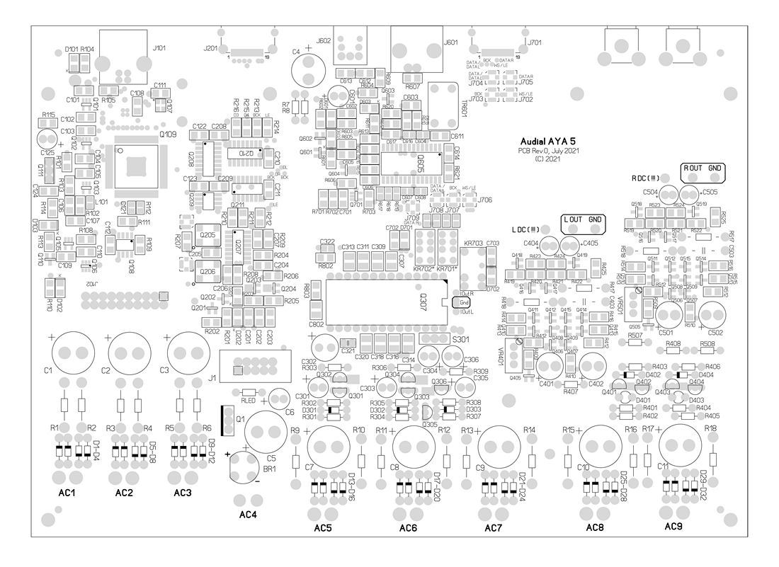
You will notice the USB stage at the left, the S/PDIF at the back, the D/A in the middle, and the output stage on the right-hand side. The S/PDIF stage is mostly SMD. The D/A stage employs SMD 1210 caps for TDA1541A DEM pins decoupling, but other than that uses mostly through-hole parts. The output stage supply is through-hole, but the circuit itself is mostly SMD (except the I/V conversion passives, which are through-hole).
Obviously, the AYA 5 has nine independent supplies.
Documents & drivers
Assembly manual and Windows USB drivers download requires login with the customer account.

Hi Pedja, I would like to take up a completed unit. i have 2 questions.
1) Is it possible to customise it with a transformer couple balance output and a capacitor coupled RCA output?
2) Will the USB Interface Card be release at a later date?
Thanks
Hi Pedja,
Is it now possible to use the Andrea Mori clock units with the separate squarers on the connectors of the Crystek clocks? If I see it correctly these are KR701-702, I cannot judge if the surrounding components hight will pose problems for the squarer boards. Is the footprint of both clock sockets the same as on Ian’s fifopi? Ian is building an alternative squarer board that consists of only one pcb with pins for both clock sockets so there is a more solid connection in order to minimise loose connections due to the weight and torque of the sma clock cables.
Will the completely build unit be delivered including the TDA1541A?
I would like an assembled board with USB section but without the crystek clocks and TDA chip.
Regards,
@ Raj:
There are two issues with output transformers in this case. First, the AYA 5 chassis was not planned to physically include transformers, and second, the AYA 5 output stage, even if it is very capable, was not tested in such an environment. And, taking into account the amount of work we already have here these days, I don’t think we will be able to address more custom requests at this time.
The USB interface board (Mk3) is rescheduled for September, but most probably we will release it too. The interest in it was not as high as in the AYA, but is about sufficient to proceed with it.
@ Supersurfer:
I am sorry, but I had to give up on including the DIL14 footprints for the USB stage clocks in the AYA 5. KR701/KR702 are the input switching relays, and USB stage clocks are Q205/Q206. They both have the U.FL beside, so external clock sources can be used instead.
It is generally possible to exclude some parts, however please note that without some of them it is impossible to test the board before shipping. In this case, without the USB stage clocks, I can not verify if everything is fine with the USB stage. With the TDA1541A chip it is not a problem, because this one uses a socket, so it is easy to replace or remove once the unit is tested.
Hi Pedja,
you mention in you text, that the AYA5 with external i2s souces operates up to 96kHz. Why ist that?
You mention as well, that only USB or HDMI can be used. What does that mean exactly? As an imput you mean?
Best regards
Ernst
Hello Ernst,
This is the limitation of the TDA1541A chip, which 6 MHz bit clock input normally sets the maximum sampling frequency to 96 kHz with the usual I2S 64-bit frame, or 192 kHz with Philips simultaneous data protocol 32-bit frame. I did find a solution that makes TDA1541A work up to 384 kHz in Philips simultaneous data mode but did not manage to solve the limitation with I2S (yet 🙂 ).
Yes, it is meant as input.
The AYA 5 input switch is basically two inputs, and it switches between the USB and S/PDIF stage (BNC and optical input are additionally switched at the S/PDIF receiver itself).
If you don’t use the S/PDIF stage, you can mount four U.FL connectors to have a direct input instead.
If you don’t use the USB stage, you can have a direct input either by using four U.FL or (one) HDMI connector (Audial specs).
Regards
Pedja, vielen Dank!
I want to order and wonder, how difficult it will be to get the i/v right.
I have an old BC547/557 (your design) and did some Hfe matching. TO92 thingies are pretty easy to match, crontrary to modern SMT critters.
Would you recommend matching?
Regards,
Ernst
And one other question, you might be able to have an answer to.
Many transformers, yours as well, tend to have primary cable isolators, that after a while tend to get annoyingly sticky. Currently I am housing all my DACs, and so the AYAII is my next candidate. It is so sticky, that I need to use a fabric sleeve in order to handle this. I really wonder why this specific isolating material is often used for this.
Best Regards
Ernst
Hi Pedja,
Can you please confirm that I can feed the dac directly in simultaneous mode through the u.fl pads (I see 4 u.fl pads), and not only I2S, to get to 192khz samplerate? Or is this only possible through your usb stage?
If I understand your reply correctly I can desolder the crystek clocks and add off board clocks through the U.fl connectors near the clocks? Will the board select the clock signal or switch the on board clocks on/off? For external clocks that are always on there needs to be an input switch.
What topology are you using for reclocking the usb stage?
How do I order the board without the dac chip? I cannot select from above 😉
Kind regards,
@ Ernst:
Yes, matching SOT-23 transistors is tedious. In such a circuit, matched transistors and resistors bring somewhat more consistent (measured) distortion numbers, but even without any matching, it will be good enough. I made a lot of similar circuits, and I’ve been both measuring and listening to them regularly, and probably more important is, the subjective performance anyhow does not change significantly, if any, or at least I was not able to notice that.
As far as I know, it can be a silicone or PVC resin (at fiberglass sleeve), and it is used for safety reasons. It can become sticky over time, but not all resins behave the same. However, this is not really my area, so I can talk to the guys on Monday and get back to you with some details.
@ Supersurfer:
Yes, you can use either Philips simultaneous data protocol or I2S, at any direct U.FL or HDMI input.
Yes, you can remove onboard clocks, and connect external ones to U.FL inputs beside. If you are sure you will use external clocks, maybe it is a good idea to install lower-cost Kyocera instead of Crystek, so we can test everything?
Yes, there is a clock switch, so you normally connect both clocks, and the AYA 5 board selects the required master clock frequency. This clock then controls the flip-flops which re-clock all the incoming signals (so both the latch and bit clock, and data signals).
Should your order options be adjusted further, it is best to send your inquiry by contact form, to get an adequate proforma or PayPal invoice.
Hi Pedja,
Thank you for your reply.
What are the mains transformer specifications for this board?
Hi Pedja,
will ‘working PCB’ option include DAC chip, or will we have to provide our own?
@ Supersurfer,
The AYA 5 requires six 9 VAC, one 16 VAC, and two windings for the output stage which should be most probably 15 VAC (I still have to tweak this part and confirm these last two voltages). Tolerances are +/-1 V.
I would recommend 0.4 A for each winding, excepting one 9 VAC (AC1), which should be 0.6 A (or more).
One 50 VA transformer can include all these windings, and my preferred option is to use one transformer whenever possible.
@ Malvin:
The working PCBs include all the respective parts, and this applies to the TDA1541A too.
@ Ernst:
The guys have confirmed, such resin-coated fiberglass is thermally way safer than say a classic PVC sleeve. PVC will stand something like 115 °C, whereas the resin-coated option will survive at least 180 °C, and will not melt at that.
So, they advise taking it like that, and living with it. 🙂
Regards
Hello Pedja,
After payment has been sent and received, will the supporting documentation be supplied to enable parts collection while waiting for your shipment?
Thank you,
Vunce
Hello Vunce,
The initial version of the assembly manual, which will include the parts list and schematic drawings, will be available in about ten days. You will receive this version, and all the updates, by email.
This manual, along with the Windows USB driver, and possible firmware update files will be also available for download at this page download area (executables are not sent by email). Access to this area will be possible with the customer’s account.
Regards
Hi Pedja,
Sounds good.
Thanks for the update:-)
Cheers
Hi Pedja,
A few quick questions:
1. what would be the output voltage (Vrms) of the Aya 5?
2. Does the Aya 5 completed unit come equipped with both the spidf and usb input stages?
3. If cost is no object, and sound quality is paramount, do you see a big difference between the Aya 5 and the S5 units? When getting the Aya 5, what might a listener miss out on when compared to the S5?
Thanks.
Hello Katrick,
The output voltage is 2.1 V RMS, typically. It is set by the I/V resistors and, if necessary, it can be set somewhat lower or higher.
Yes, the completed unit normally includes USB and S/PDIF inputs.
In its topology, the AYA 5 comes closest to the S DACs. Its USB and S/PDIF stages are similar to those of S5, and its I/V stage is similar to the one used in The Model. I am, of course, familiar with all these circuits and parts, and their sonic properties, but I am also still to hear the final AYA 5 prototype – hoping to have one and possibly start tweaking it in a week or so. Then I will be able to provide the final audio characterization report too.
Regards
Thank you very much Pedja for such a quick reply. I have been using dacs which have around 2.0-2.4vrms and in my tube setup, i find the gain not so high enough for a good drive. I have changed my output transformers to change i/v and hence raise the output voltage. Hence, i would like the Vrms to be around 3.5vrms. Is it possible to set the gain this high in the Aya5 without losing fidelity?
I will be very keen on hearing your impressions on the final version and the comparison with the S5. Please keep us posted. I can accordingly take the decision.
Lastly, one more thought has been bugging me and I feel no better person than you to address it – does having multiple tda1541a chips in a dac (say 2 or more chips) have any advantages over a dac with just one tda1541a chip?
Thanks
Yes, the supply voltage headroom of the AYA 5 output stage is enough so we can increase the output to 3.5 V RMS. I am not sure how much the performance might change, but it is likely not much (quick simulation shows only a couple of dB higher second harmonic, which is a good sign).
As for two TDA1541A, first, I generally don’t think the active parts paralleling is a way to improve their performance. Moreover, with TDA1541A the layout would be a mess because each chip requires its own DEM pins decoupling caps. On the other hand, the balanced topology may be fine, but you end up practically with two DACs.
Hello Pedja,
Payment has been sent!
Thanks
Thanks, I can confirm it is received.
As for the current state of this project, it is still underway, so the pre-ordering remains possible for another week or so.
Anyhow, you can expect to receive the parts list and schematic drawing previews during the upcoming week.
Hi Pedja,
We look forward to hearing from you regarding your impressions of the final prototype of the Aya5 and its comparison in terms of sound characterisation with the S5!
Even though things developed very fast this summer, and the initial AYA 5 design was finished quite quickly, we did not unfortunately manage to complete the prototype as planned (and synchronize everything before some of my co-workers went on vacation), and there will be something like 20 days delay with the AYA 5.
Apologies for this.
Everything else remains the same, so there are no other changes in plans.
In the interim, you can still order the AYA 5.
Thanks for the update Pedja:-)
Please tells us your impressions about AYA 5 DAC vs S5 DAC …
I’m excited to hear your version of a NOS dac. Can my version have rca output hotrodded to 3.5Vrms too? If not that’s ok. 🙂
The AYA 5 follow-up will come by the end of this week. I have taken this request for a higher output voltage into account too.
Thanks everyone for your patience.
Hi Pedja,
I’d like to ask if there are some major differences to AYA 4 with the USB stage and Reclocker stage.
Is the main difference only better clock is used in AYA 5 (on the USB side as I understand or also the clocks in the reclocker?), that there are now no ‘downsides’ of the 352x clock, so it could be also replaced in AYA 4 with same result? (I use upsampling so the high clock frequencies are in use in my case)
As I did for myself some ‘ultimate’ 😉 mods in the reclocker stage for the USB-only with good results (like passing to the DEM reclocking the clock directly from the flipflop inverted output, stacking separate flipflop for individual latch or clk reclocking, omitting the multiplexer for the clocks so feeding only directly the 44.1x clock, etc),
so I think the better option for me to try the AYA5 discrete output stage would be just to order the bare PCB and populate the output stage and connect to it D/A output from the AYA4.
Or there are some also other important changes somewhere else?
Greets
Hello Bartek,
The USB stage and reclocker generally remained the same, and apart from adding U.FL connectors for external clocks, the only progression there this time is about the parts. The audio master clocks are now Crystek (the USB decoder 13 MHz clock is also changed with the smaller footprint part, but this one is mostly irrelevant for the audio performance), and lower noise transistors are used in these master clocks and reclocker supply.
So, if you want to use only the USB source, and with all the tweaks you have already done in your AYA 4 USB stage, it would be most effective to stick with your AYA 4 digital part, and move to the AYA 5 for its output stage. There is a slight improvement in the AYA 5 D/A stage supply too, so you might try it once too.
Regards
Dear Pedja,
Thank you for keeping the TDa1541 alive. Some questions from me:
If I am not mistaken then you will soon open up the store for a USB board?
If so I assume I can later use this board together with an Aya 5 board?
If I just buy the PCB, are the SMD’s around the TDA1541 included. I don’t need the output stage (yet).
Is the supplied TDA fromTaiwan, one of the last series?
Keep up the good work.
Hello Patrick,
It was not an easy decision for me, but due to the latest parts availability difficulties, I will probably have to give up on releasing the USB board for now, and wait with it for some better time. And I hope the better time could be next spring. I will post the final decision and more details next week.
That board, just as previous Audial USB interface boards, would be of course easy to use with AYA 5.
Out of the two general DIY options, “Populate the PCB” does not include any part in the D/A stage, while the “Working PCB” option includes all the parts in the D/A stage. The only SMD parts there are TDA1541A DEM pins decoupling capacitors, which are 1210 size, and supposedly not that hard to solder by hand. (The synchronous DEM clocking circuit parts are also SMD, but this circuit in the AYA 5 is optional.)
Unfortunately, late Taiwan made chips are a long time gone. I come only to some piece from time to time, but that is really scarce.
Regards
So, the AYA 5 prototype is done, and here are my thoughts and verdicts on its performance.
First, objective performance. The distortion of AYA 5, at higher levels mostly associated with the output stage, got about 20 dB better than that of AYA 4. The prototype unit at -6 dBFS showed 0.007% at one, and 0.015% at the other channel.
This was achieved by using specified parts, without any matching (the parts were from the same production run, though). I will have to measure more units before I speak exactly about statistical distribution in production, but with about two decades of experience with similar output stages, I would expect the distortion figure to sit mostly between these two.
Also, with the same experience, I can also say that such variations are quite normal for such (symmetrical) topologies without feedback, and you can notice the same even with monolithic circuits, with intrinsically better transistors matching (indicative with AD844, and in some degree visible also with the OPA861).
So, one channel, -6 dBFS, 1kHz dithered sinewave, 0.007%.
The other channel, 0.015%.
Subjective impressions are following.
Impressive results Pedja!
I would guess most of us will not be able to play more than 80db of resolution in our living rooms so this will be more than adequate.
Looking forward to the subjective results!
Regards,
It’s great that the prototype was working and some comparison with the flagship s5 product, maybe some reference to older versions like the S model.
@ Supersurfer: Thanks. In my experience, speaking about the subjective performance of such feedbackless I/V circuits, the -80 dB (0.01%) distortion is the point where the glare disappears, and where you get the full resolution.
For instance, speaking about the OPA861 I/V, it is all smooth, natural, and dynamic, and generally great (yet simple to build) I/V stage, but not that clean and precise, and it did not have that precise soundstage like S DACs.
Now, what the AYA 5 discrete output stage brings is a subjectively the same clean performance, and the resolution about equal to S DACs.
Also, it has a great soundstage, that makes you tell the real and unique acoustics of the bigger or medium strings setup (Khadja Bonnet, The Visitor, 2015) from the one emulated by the artificial means i.e. electronics or processing of any kind. If I should spot some weakness: some performers are not the same tightly locked in their space, as with S5. I am not sure if such things you will call “minor”, but I am sure it takes a very good rest of the system to reveal this. (I consider my Audial A20 amplifier and Quad ESL-63 such a system.)
Tonally, the S5 is still more rich and spicy, but here I don’t talk about big differences. Also, I believe it is a question of time when someone will tell me to like the AYA 5 tonally better. Anyhow, the bass is the same deep, and dynamically, and regarding the resolution and decay, the AYA 5 does not lack anything, speaking in absolute terms.
@ Artur: I do not have any Model S with me for direct comparisons, but still keeping it very well in my ears, and using the same S/PDIF source, the AYA 5 is probably a bit more alive, while the Model S might be tonally somewhat more smooth, and more powerful at the bottom end.
And here is the actual output stage, mostly responsible for these steps ahead we made with the AYA 5.
(Click on the picture to enlarge it.)
In reply to the request for a higher output level:
I checked the AYA 5 with 2k4 I/V resistors (also Allen Bradley), required for 3.5 V RMS output, and technically speaking I see no problem using the AYA 5 this way. The distortion performance remained very similar, even though at the given level some components varied for a couple of decibels. And it was interesting to see, with output set to 3.5 V RMS, the even order components actually dropping down for a few decibels at higher levels.
Subjectively, the performance is again similar or the same. My impression was that a higher output voltage brought a somewhat more enthusiastic presentation, but then again, the difference was small (to none).
Dear Pedja,
This sounds very promising! Looking forward to receiving the board. When do you think they can be shipped?
My system is also extremely resolving with full directly heated triode amps and open baffle field coil loudspeakers. I currently use a balanced TDA1541A dac with Sowter output transformer fed in simultaneous mode from a fifopi, Andrea Mori clocks and usbridge signature streamer.
I am keen to compare this with your design.
Your choice of resistors indicates a lot of knowledge; not one component seems selected arbitrary. R522 or r518 is the IV resistor?
Looking at the output stage is there dc decoupling by the electrolytics near the output?
What does the pot do?
Regards,
Hello Pedja,
Well done 🙂
Is there a difference between the populated Aya 5 USB stage and the planed standalone USB about its electronic parts apart the waited option of a DIL14 vias for external clocks and an optional greater voltage or curent supply for the crystals…usually 3.3 V ?
Great report about your new discrete analog stage with diode and no Darlington(?) with as good dynamic than the previous Aya but better soundstage and tones. I noticed a smd resistor at the output resistor. How is the difference with the Good Allen Bradley R used here before ?
Could we still use direct coupling by triming the pots please ?
Do you find the digital piwer stage better also better without The Darlingtons …can still see them in your 2020 on shelf flagship photograph ?
@ Supersurfer:
R417/R517 are I/V resistors, while R418/R518 carry the signal down to the output buffers.
The blue trimmers set the current that nullifies the output offset. The TDA1541A output current is unipolar -4 mA (current sink), and 2 mA current sources are used to center this current around zero, and thus make it bipolar ±2 mA.
Yes, the output is coupled by two back-to-back Elna Silmic II caps. Those current sources normally keep the output offset low, but different scenarios may produce excessive voltage there, so I would not advise direct coupling for this DAC. At least not if you use different sources, so the TDA1541(A) is not constantly clocked by the proper signal.
@ Eldam:
Thanks.
No other differences in sight for now, but due to a critical availability of some parts (read: increased parts costs), the next USB board release will be postponed for the next year.
The output stage supply is still the shunt, but no TL431 is used anymore.
Regarding SMD carbon resistors, they are great when the layout is tight (or you want it like that), but I am still not ready to ditch AB completely.
Yes, I found it worthwhile going with a lower noise option in the TDA supply. The AYA 5 is here very similar to the S5.
Regarding the shipping:
I still have to check some minor issues, but the project is practically finished. As I am about to announce the official postponing of the USB interface board for the next year, there will be a few days still, in case anyone wants now to place an order for AYA 5 instead. And then we will start manufacturing.
Unpopulated boards will be shipped in about 20 days, while other orders will be shipped a bit later. It is October already, but I expect everything processed before the end of November.
Many thanks for the inputs. I particulary like the AB resistors I discovered in the AYA 2 2014 millesime I use between the I/V and the buffer as advised and also at the output in serie after the buffer.
For the ones thinkin a 16/44.1 has not resolution enough, I can testimonie I can hear in my system for the last AB resistor a difference between 4 matched AB resistor : a pair in 1/4W the other in 1/8W.
I use direct coupling in my 2014 Aya cause I can (the pre has DC blocking at the input) and for a strange reason I can not explain the 1/8W is giving a difference, big enough and in the good towards a better hearing result ?! I think I inputed that already in the blog if my memory serves me well. (I think it’s due to the thiner wires of the 1/8W version and I’m glad the DAC and my system are clear enough to perceive such very low difference between two close parts)
So I asked why they were not here in the 5 . But yes it is tight indeed due to the smd transistors. The smd resistors are very neutral from the few i heard in DIY buffers and I also see in the upper photograph you also introduced 2 MELF resistors in this stage in a precise area as well… I am sure it’s not by chance :).
Hello Pedja, I have bought a board without transformer. Can I still add one to the order?.
With regards,
Patrick Kers
I have 2 otrrodial transformers, 15V ac and 9 V ac. I don’t know the required specs.
Hello Patrick,
Yesterday I have sent the assembly manual to all the AYA 5 customers’ e-mail addresses, and you should have received it too. All the necessary data is there (hopefully, as it is 32 pages), including transformer specs.
This manual is also available for download on this page (at the bottom of the initial post), but as opposed to the user manual, the assembly manual and Windows USB drivers are accessible only to the AYA 5 customers. So, should you need any of these downloads, you will need an account at the Audial website, and once you create one, or if you already have it, please let me know (by e-mail, or you can use the contact page) so we can grant the access.
Regarding the transformers, they are already in production, but there will be several spare pieces, so please let me know if you are interested.
Regards
Your build guide is fantastic, thank you Pedja!!
I’m really looking forward to this project.
Cheers!
Any news about the shipment?
By now, the orders including unpopulated PCBs and toroidal transformers are shipped.
I expect to have the first units completed by the end of this week.
I will notify you (all) by e-mail before shipping. Thanks once again for your patience.
When can re-order ?
Currently, it is a priority to dispatch the previous AYA 5 orders, and we are busy with that.
It may be possible to re-release one smaller series sometime in January or February, but it is no promise. I like this project very much, and I see some interest in it still, but the parts shortage continues, and we’ll see where we are at in a month or two.
I understand. I’m waiting for information, because I’m interested. I would like to ask one more question why you decided to use Allen Bradley resistors, they are very capricious and sonically also not is wow (great)
I don’t agree on that, obviously.
I agree with Pedja,
Allen Bradley is a very good sounding resistor when used in the right spot. Pedja’s choice of components like these is where you can see the efforts he takes to get to the best and most balanced sound signature (it is not all about measuring you know). This is something you hardly see in the audio and high-end business but is what makes a design stand out from the masses.
You could also ask a similar question: why use the old and obsolete Philips TDA1541A instead of for instance a modern ESS ES9038???
Regards,
New ones float, to get rid of moisture you have to keep them in the oven, for me they are half the product. In order for them to maintain the parameters, it is best to insulate them. But I respect your opinion.
Here is a short update on the current state of the AYA 5 delivery.
Unpopulated boards accompanied with toroidal transformers are shipped some time ago.
The previous week we started shipping populated boards and completed units. In the next few days we’ll also start shipping the orders including EI transformers. It will take some time until this work is done, but I expect to have all the orders, except the completed units in black chassis, shipped in the next 14 days.
The units with a black finish will start shipping about 10th January.
Also, the AYA 5 DIY assembly manual will be updated in the next few days, and I’d strongly recommend looking at this revision. As before, you (the customers) will receive it by e-mail, and then the same document will be available for download in the dedicated download area.
Once again, thanks to everyone for your patience with this project. We’ll continue to work, and won’t take a break until this work is done.
In the meantime, wishing you happy holidays!
Looking forward to my aya5 dac. Just set up my passive preamp to prepare for the aya5 to arrive. No more digital attenuation for me 🙂
Moving the volume control after the DAC is a good step, for sure.
In addition to all the delays we experienced with this production run, the black chassis manufacturing took even more, but we will start completing the units in black chassis the next week.
dear Pedja,
I finally received the board and transformer. It looks really nice. Great work.
I am now in search of the required components.
Can you (and perhaps other audial enthusiastics) provide some websites to purchase the required components?
I know Farnell, Mouser and TME. The Elna Silmics are not easy to find.
Any help is welcome.
With warm regards,
Patrick Kers
Thanks, Patrick. I am glad the package is with you now.
My Elna Silmic caps come mostly from Digikey, but Mouser also sells them. Some values might not be available sometimes, though.
https://www.digikey.com/en/products/filter/aluminum-electrolytic-capacitors/58?s=N4IgjCBcoLQCxVAYygMwIYBsDOBTANCAG4B2aWehA9lANohwBMcAnBALqEAOALlCCAC%20woA
https://eu.mouser.com/c/?marcom=165227470
Also, one general information regarding the shipping. While most of the orders (something like 80%) are already shipped, we still did not finish this work. In addition to all the delays we had, in January Covid came to my family – we are all apparently fine now, thanks, and I personally was not infected – but for all of you who received the mail regarding your order in the last ten days of January or so, please consider additional 10-14 days delay.
Also, since I am receiving additional inquiries for AYA 5, please note that we will not accept more orders until all the previous ones are processed. This is a good project, and I would like to make another run, however only once the previous orders are shipped, and I cheek the parts stocks and availability, we might proceed with it.
Thanks.
I waiting for the next cycle, the tda1541a from the Y2 series is already waiting in the drawer.
Hi, how is the parts and order situation atm?
Many thanks
At this moment we are still dispatching some of the previous orders, and this work should be done in about ten days.
Then, so sometime in April, we will announce another small series, but this time the offer will probably include only completed units and completed boards.
The parts shortage is getting harder almost every week indeed, and that is what would be viable for now.
Pedja, thanks for all your help. Our AYA 5 (purchased as completed & tested board w/o TDA1541A as my Christmas 2021 present from my family to me) is up and running. I implemented the isolation transformer option and have a 2nd set of output capacitors on a hobby board set up for easy experimenting. Everything else is Audial factory setup. What I really liked about getting a 100% tested board is the 4 pages of THD tests showing that this DAC is super clean and built right. I don’t have the software to test. It’s a huge relief to know this DAC is done right!
The AYA 5 is a great value & it may push me into purchasing the S5 someday.
Cheers, Aguaazul (A.K.A. Randall)
Here’s a link to some (too many) photos (saved on google photos – no sketchy site):
https://photos.app.goo.gl/2hgSbtnXAkxPHXnG8
It is a pity that only ready-made kits will be available, I would like to give other capacitors there and experiment with resistors.
@ Randall,
Thanks for posting.
Next days there will be another assembly manual update, and it will include one relatively simple way to improve both the objective and subjective AYA 5 performance.
@ Artur,
The parts’ availability is terrible these days, and it makes it about impossible to recalculate and produce cost-effective partially mounted boards.
As for using different capacitors and resistors, I would always advise starting with recommended passive parts, but supplying a complete kit with some exceptions here might be possible.
I can’t believe how huge an improvement the Aya 5 dac was when I put it in my system. Finally I’m getting the sound I always wanted. Individual instruments are so distinct now and real sounding. Thanks Pedja!
Thank you, it is great to know that.
I have a question, what power should a 50VA isolation transformer be for a dedicated transformer or 1: 1 is enough. Should it be oversized 150%, around 75VA?
There is no need to oversize the isolation transformer. Sometimes, it can be even lower power than the voltage transformer. But in most cases, it is best to have these two transformers of the same power.
Thank you for the answer, I have another one . I have regarding selector. How many way end positions rotary switch should have. Please give some example.
Generally, the input switch should provide one “off” and two “on” positions. Basically, the “on-off-on” toggle will work, but the rotary switch will probably look better on the front plate.
In the AYA 5, I am using the Lorlin CK rotary switch, with pin A used as an input, pin 1 wired for BNC, pin 2 left floating for OPT, and pin 3 wired for USB input. These switches include “stops”, so you can set say the 4-way part to operate with three positions.
https://lorlinelectronics.co.uk/product/ck
HTH. You will, of course, find the input switching scheme details in the manual.
Great, I love such answers. Specific explained, thank you.
First question, I am using cd transport there i have a coaxial output signal, could it be possible to mount an input plug with this standard. The second question is whether it would be possible to output the signal to another analog, e.g. tube, directly from the tda1541a. I saw the output of outL and outR and GND there.
The AYA 5 does include coaxial S/PDIF input, and you can generally connect any source that complies with the S/PDIF standard.
Please note that this AYA 5 input employs the BNC connector, to match the proposed 75 Ohm impedance. And I would always recommend using the whole S/PDIF interface that fulfills this impedance requirement, but if it is not possible, and if your source uses an RCA connector (which is most typical), you can simply use a cable with RCA on one and BNC on the other side (or even RCA to BNC adapter).
Yes, you can use these pads to connect the other output stage. In this case, you will have to disable the onboard I/V stage, by disconnecting its power supply and removing the input transistors pair.
Can the optical socket be replaced with the rca? I would not like to replace the plugs in the rca cable. I could change the BNC socket to RCA, but I prefer to leave it to be able to use the streamer. I do not want to use the adapter, they are of poor quality. I / V stage, I disconnect not only ac8 and 9 power supply but I have to remove a pair of input transistors q401, q403, q506, q507?
I am not sure if it is practical, but it is certainly possible to omit the optical receiver (you will also have to remove C613) and connect another coaxial input instead. You will of course need at least some coupling capacitor for this input (if not another S/PDIF input transformer).
I was actually referring to the I/V input nodes, formed by Q408/Q409 and Q508/Q509 emitters. By disconnecting AC8 and AC9 these will nominally turn to high impedance nodes, however there are a couple of associated issues which make me more quiet if these transistors are just removed. The same advice would apply also to the current sources Q405 and Q505.
Another solution would be to cut the traces leading from TDA1541(A) to the onboard I/V.
Hi,
My Aya 5 EI transformer had no start/end markings on the primary or secondary windings. How do I confirm this? Thanks.
Hello Vunce,
Only toroidal AYA 5 transformers are marked for their primary windings’ starts and ends.
EI transformers’ primary windings’ starts and ends are visible from the outside. You should be able to see this if you look from below.
As for the secondary windings, neither toroidal nor EI AYA 5 mains transformers are marked for their starts and ends. So, should you want to determine the secondary windings starts and ends, you would have to use the signal generator to feed the primary, and to observe the waveform on the secondary windings.
HTH
Thanks Pedja.
I’m mostly concerned about proper primary phase because of parallel connection for 120v.
Regards
At EI transformers, looking at primary leads from left to right, typically the first is the start and the second is the end of the first winding, and the third is the start and the fourth is the end of the second winding.
Consequently, to have these windings operate in parallel an in phase, you will have to tie together the first and the third lead as one, and the second and fourth lead as another connection to the 110-120 VAC mains voltage.
I have a question, has anyone used a raspberry pi4 connecting usb to aya5 (moode audio software, volumio). I tried but the software does not see the usb port, probably no drivers.
Frankly, I do not use Raspberry Pi and am not familiar with it, but hopefully someone else can help.
Thanks Pedja, I think I need Linux drivers.
I’m experimenting all the time, I replaced a few resistors and capacitors. It is worth replacing styroflex with NOS Jansen and give something better for resitors 18r I have shinkoh and 10k AN tantalum. I also took care of the section around the tda1541a. Effect – increased accuracy, larger scenes and better bass modulation. For now, I have decided to slightly refine the basic version. Then I will try other analogs: pass d1, tube analog or other on discrete elements.
The biggest problem is very small places (pads) for other elements. It’s must to be mounted on the bottom of the pcb. There is great potential in this solution.
I have a question regarding the tda1541a itself, you have a lot of experience. Is the version of the tda1541a with the inscription Taiwan in your opinion optimal?
Hello Artur ,
I would like hear raspberries pi connecting aya5 dac ,now not problem right ?
We are same boat .
Hi Myint,
A bit weird because aya5 uses an xmos chip which is supported by raspberry pi4. He can’t solve the problem yet. Why is it not visible.
Hi Myint,
A bit weird because aya5 uses an xmos chip which is supported by raspberry pi4. He can’t solve the problem yet. Why is it not visible.
I have another DAC with the same xmos chip (pcm1794) and it works there without any problems.
I also use a shield for raspberry pi2aes after BNC works fine.
When I’m done collecting other Aya5 parts, and I’ve already made a lot of progress, I’ll go back to USB.
Hello artur ,
I also waiting my aya 5 dac ,They are on the way .normally Xmos Usb is no problem with raspberry pi.
Thanks
Merry Christmas Pedja,
To you and yours.
Kind regards
Shane
Thanks, Shane.
Wishing you a Merry Christmas, and happy holidays to you too, and everyone here.
Pedja
If this is interesting or helpful, using the 5V supply as an example:
I noticed the zener diode datasheet shows improved noise performance at higher currents, from 10 JFETs (CCS) all except one measured 20-22mA which looks good wrt the graph in the datasheet.
The diodes measured with 300mV variation across 10pcs (5v67 to 5v95), using the lowest measuring diode the regulated output voltage for values of current at the 1541A datasheet (typical and maximum) showed just 35mV variation. With the load current set half-way between typical and maximum, increasing the value of R308 reduced the output voltage to very close to 5V.
Also, yet unsure if it will make any appreciable difference:
https://www.diyaudio.com/community/threads/simple-no-math-transformer-snubber-using-quasimodo-test-jig.243100/
With AYA2 toroidal power transformer there was 7x reduction in ringing with 12R+0.15uF//0.01uF across each of the lower voltage secondaries, and 13.5R+0.15uF//0.01uF across the higher voltage secondary. Note: this is not the transformer ringing of itself, but when injecting a square wave into a winding.
Cheers
Shane
Thanks for posting, Shane.
Yes, it is highly interesting and helpful, and certainly points out the room for improvements. I would guess the effects will be quite audible.
For all of you whose AYA 5 unit or board was shipped in August or September last year, and who possibly experienced difficulties with the USB connection, I would have to inform you that this problem may be caused by an unstable 3.3 V regulator in the USB stage. The problem is not associated with the design but with the regulator IC itself (which, in my defense, is the IC I use for more than a decade – so yes, it is simple like that, a flawed series), but I will anyhow have to apologize for the inconvenience, and it will be my responsibility to fix this.
Some of you were already notified about this by e-mail, but soon I will send a circular e-mail to all of you whose AYA 5 DAC might be affected by this problem, and this mail will include more details.
Hi Pedja,
I picked up an used year old unit in April’23. Could you elaborate on usb connection issues , one issue I face with USB is a loud tick when each song change happens & also when switching input back to USB. Is this relevant in any manner ?
What you describe is likely not associated with the USB connection, but is a phenomenon associated with Philips simultaneous data protocol. Namely, since this protocol employs the offset binary data format (and not two’s complement, used in I2S), every playback start or stop, or input switching, may produce a certain pop or click.
Not all sources manage the data stream the same way, and you probably will not experience any pops if you use Windows and the Audial USB audio driver.
Unfortunately, the only way to fully and unconditionally solve and remove any pops or clicks (especially when it comes to the input switching) would be to use the output muting circuit. Such a circuit would in turn compromise the sonic performance, so I settled on leaving the output as is.
Regards.
I saw that there will probably be more Aya 5 for sale this year. Is it known yet when that would happen?
Yes, there is such a plan. Sometime in September would be realistic.
Also, here is the information for everyone who had a problem connecting the AYA 5 to some Linux-based sources.
It turned out that some LMS-based streamers are not compatible with multichannel devices. While I would always ask the streamer manufacturers to provide appropriate patches and thus improve their device functionality, we recently also provided the firmware migration file that “rolls back” the AYA 5 USB stage to 2-channel.
The file and instructions are in the download area of this page, accessible with the customer’s account.
For more information, please see this post:
https://www.audialonline.com/blog/multichannel-or-2-channel-usb-stage/
Has anyone tried to connect to iPad?
Lightning to usb
The information for those using a Windows machine as a USB source, and possibly experiencing problems starting the playback at 44.1/88.2/176.4/352.8 kHz Fs – instead, the playback might need to start first by using the other string of Fs (48/96/192/384 kHz) – there is a firmware update that solves this issue.
The update files, for both 2- and 4-channel operation (f/w v3.80 and v3.81, respectively), are available in the downloads area.
Another limited series of AYA 5 Revision B is now available for ordering.
https://www.audialonline.com/blog/aya-5-revision-b-2024/#ordering