

As stated from the very beginning, a standard input stage of the Model A is a low impedance shunt potentiometer. So, how did it come this way, and why do we use such a radical solution that obviously counteracts the usual approaches?
The answer is simple, and again as stated from the very beginning, is: because it is the best sounding “pre-amp” there is. Looks simple? In fact, it is, but let’s take a closer look at it.
Firstly, for the record, “normal” potentiometer wiring looks this way.
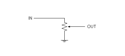
So, its bottom side is the ground, and its upper side is the input signal. The wiper moves between two sides, and carries the signal to the next stage. Impedances are obviously not constant, but can be kept within an acceptable range. With a logarithmic potentiometer, the attenuation curve will be real logarithmic too, and conductive plastic potentiometers are usually made in a way that really fulfills logarithmic curve requirements. Furthermore, conductive plastic pots inter-channel tracking is very good, at all levels. And their sound is relatively fine too, so in many audiophile constructions, such conductive potentiometers are no-brainers, for decades.
Still, we want the best. And when I say this, I consider classic passive potentiometers of all kinds, different stepped attenuators, transformer based volume controls, and less conventional stuff such as LDRs, with or without different active stages, as a competition. In my view, the best chances here still have digitally controlled stepped attenuators (or so-called “digital potentiometers”, please search around for a simple DS1802 solution I published years ago), but this would be the topic for the other day.
And my views haven’t changed since the Model A release, so I can only repeat: “the best” is still the low impedance shunt potentiometer.
As you might already know, a shunt pot looks like this.
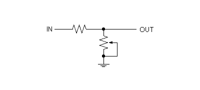
Such a configuration is sometimes considered advantageous for having a fixed resistor at signal path (*), however it is usually abandoned both because its impedances are way more problematic (in the common engineering sense), and because its attenuation curve can not be fully logarithmic – the series element is fixed resistance, so only shunt part can behave logarithmically. So it is rarely used, usually only in a high impedance environment, with relatively high series resistance, that does not load the source very much.
It was Malcolm Hyde and our work on Gramofone devices that helped me realize how wrong such an understanding of shunt potentiometers, and probably the potentiometers in general, actually is.
The key point was: the lower the series resistance we used, the better the sound we had. And the best things start to happen at and below 1 kOhm! (**)
And obviously, to come across this point, you need a source that can drive such a sub 1 kOhm load. OK, Audial DACs are ones of that kind, but all this can look strange anyway. The question we obviously have is: what makes the potentiometer sound better in this case? And it is also interesting, these findings apply to both conductive plastic and cermet potentiometers. So, a higher current flowing through the potentiometer wiper, which is unsoldered, moving contact? This is still a sort of open question to me, but it looks like that. And the potentiometer in shunt mode, with low series resistance, is probably the only usable configuration that can force a higher current to flow there.
But, at the end of the day, it is not even necessary to think about the reasons – you can just take it like that instead, and enjoy it.
As for the potentiometer itself, cermet is clearly preferred sound-wise. In practical use, it can be tricky, though. A more detailed explanation follows.
_____________
* – You can even find the claims that it is only a series element that counts, but it is of course not correct: the signal that “leaves” the volume control is the quotient of its series and shunt parts.
** – Of course, lower series resistance takes a lower value potentiometer, which will also solve most of the problems with shunt potentiometer output impedance.