

A-link (PCM / I2S direct) specifications

Quote from Eldam on 3 February 2024, 3:46 AMReaded this with interrest.
I strongly reduced my time into diy audio, but I really love one day to have a system with an active speaker driven from a multi DAC.
I do not know how it works but HDMI is more and more everywhere as is USB-C connectors too. Is it technically feasible with XMOS interface to have three I2S output for three DACs like the AYAs (or S5) and a single input USB/HDMI from the computer for active filtering ? I assume the digital streaming is multiplexed in time in the standalone cable from the computer. then each DAC will feed each channel, bass, medium, treble, to have an active filtered system. And not ADC, all from the computer with a fast industrial isolator chip to isolate the noise of the computer ground ?I2S migth be a problem to dispatch the three AYAs inputs, but LVDS protocole could be ok and more resilient for the TDA1541A which is ok with low voltage at its inputs chip made (can of worms here perhaps?)
What you think ? I mean conceptually speaking.
Regards, Eldam
Readed this with interrest.
I strongly reduced my time into diy audio, but I really love one day to have a system with an active speaker driven from a multi DAC.
I do not know how it works but HDMI is more and more everywhere as is USB-C connectors too. Is it technically feasible with XMOS interface to have three I2S output for three DACs like the AYAs (or S5) and a single input USB/HDMI from the computer for active filtering ? I assume the digital streaming is multiplexed in time in the standalone cable from the computer. then each DAC will feed each channel, bass, medium, treble, to have an active filtered system. And not ADC, all from the computer with a fast industrial isolator chip to isolate the noise of the computer ground ?I2S migth be a problem to dispatch the three AYAs inputs, but LVDS protocole could be ok and more resilient for the TDA1541A which is ok with low voltage at its inputs chip made (can of worms here perhaps?)
What you think ? I mean conceptually speaking.
Regards, Eldam
Quote from Pedja on 3 February 2024, 6:23 PMHello Eldam,
That is exactly what I meant with this connection. It includes four data lines, so in I2S it can carry up to eight channels (two channels multiplexed in each data line). In simultaneous data mode, each channel requires its line, so it is limited to four channels.
The previous year's USB interface board release (Mk3) supports either eight channels in I2S or four channels in sim. data mode.
Differential signaling would halve the channel count. You can consider if the LV (Low-Voltage) part of LVDS could be welcome or not for TDA1541(A), but going differential will also bring you again to jitter introduced by redundant (IMO) stages.
Regards.
Hello Eldam,
That is exactly what I meant with this connection. It includes four data lines, so in I2S it can carry up to eight channels (two channels multiplexed in each data line). In simultaneous data mode, each channel requires its line, so it is limited to four channels.
The previous year's USB interface board release (Mk3) supports either eight channels in I2S or four channels in sim. data mode.
Differential signaling would halve the channel count. You can consider if the LV (Low-Voltage) part of LVDS could be welcome or not for TDA1541(A), but going differential will also bring you again to jitter introduced by redundant (IMO) stages.
Regards.
Quote from Pedja on 3 February 2024, 11:32 PMYes, sure. In such a scheme, I would be only cautious with tweeters, because simultaneous data mode can, because of its offset binary data format, introduce more pops and clicks than I2S (for instance, if you switch the input), and put directly connected tweeters at risk.
Yes, sure. In such a scheme, I would be only cautious with tweeters, because simultaneous data mode can, because of its offset binary data format, introduce more pops and clicks than I2S (for instance, if you switch the input), and put directly connected tweeters at risk.
Quote from Pablo R on 18 April 2024, 6:46 AMQuote from Pedja on 23 August 2023, 4:30 PMIt is two years since I published the A-link specs, and by now, plenty of Audial DACs with this interface have been shipped.
Some customers asked if these units may be compatible with other manufacturers' I2S sources, using HDMI connectors but nominally not complying with A-link.
The A-link pinout is indeed similar to the other I2S standards using an HDMI connector. The most important, when you look at it, are DATA (a.k.a. SD), BCK (a.k.a. SCK), and WS (a.k.a. LRCK), and they are at pins 1, 4, and 7, respectively. If your I2S source uses such a pinout, it is possible that it may work with A-link too. Please note, if your source pin 1 is Data (SD) negative, the signal polarity will be inverted (with very negligible DC offset as well), and if pin 7 is WS (LRCK) negative, the channels will be reversed (and there will be a delay between channels equal to 1/Fs, which will be also negligible, but only so long as you don't listen with headphones), but in terms of the fundamental operation, it will still work.
What still matters is the voltage.
By proposing the A-link, my main goal was quality. For this reason, I proposed a connection that uses "native" (CMOS/TTL) voltages. Practically speaking, the CMOS/TTL nowadays means mostly the signal swinging up to 3.3 or 5 Volts (triggering around half of this voltage for CMOS or around 1.3 V for TTL).
If your source uses LVDS, it is important to understand that the LVDS swing can be anything above 100 mV and is typically between 200 mV and 400 mV (differentially, loaded), although it can be also higher. Its typical offset voltage is 1.2 V, so what you may expect as a typical LVDS source is a signal swinging between 1 V and 1.4 V. LVDS, of course, also implies the negative poles, but the A-link DACs will simply ignore them.
Audial A-link specifies 2.3 V as a minimum for the high state. Audial DACs may work with a bit lower voltages, but such an operation is not guaranteed. So, if your source is nominally LVDS, you should contact the manufacturer and ask for information on the actual output voltage swing of their sources.
Unfortunately, I am not in a position to acquire different I2S sources to check if they will work with A-link or not, sorry. However, according to the feedback I had from the customers, I can report that the following units worked well with Audial S5 DAC A-link input.
XingCore AF200 USB Bridge ("Reverse the Phase" should not be checked) - credit to Bernd
Pi2AES 2.0 (W1 jumper 5-6 out) - credit to John
Everyone else who successfully tried Audial DACs with other manufacturers' sources with such an interface is welcome to report here.
I can confirm Mercury Streamer V2 (HDMI LVDS output) works with an Audial S5 (HDMI A-Link input) with the 4 dip switches in the off position
Quote from Pedja on 23 August 2023, 4:30 PMIt is two years since I published the A-link specs, and by now, plenty of Audial DACs with this interface have been shipped.
Some customers asked if these units may be compatible with other manufacturers' I2S sources, using HDMI connectors but nominally not complying with A-link.
The A-link pinout is indeed similar to the other I2S standards using an HDMI connector. The most important, when you look at it, are DATA (a.k.a. SD), BCK (a.k.a. SCK), and WS (a.k.a. LRCK), and they are at pins 1, 4, and 7, respectively. If your I2S source uses such a pinout, it is possible that it may work with A-link too. Please note, if your source pin 1 is Data (SD) negative, the signal polarity will be inverted (with very negligible DC offset as well), and if pin 7 is WS (LRCK) negative, the channels will be reversed (and there will be a delay between channels equal to 1/Fs, which will be also negligible, but only so long as you don't listen with headphones), but in terms of the fundamental operation, it will still work.
What still matters is the voltage.
By proposing the A-link, my main goal was quality. For this reason, I proposed a connection that uses "native" (CMOS/TTL) voltages. Practically speaking, the CMOS/TTL nowadays means mostly the signal swinging up to 3.3 or 5 Volts (triggering around half of this voltage for CMOS or around 1.3 V for TTL).
If your source uses LVDS, it is important to understand that the LVDS swing can be anything above 100 mV and is typically between 200 mV and 400 mV (differentially, loaded), although it can be also higher. Its typical offset voltage is 1.2 V, so what you may expect as a typical LVDS source is a signal swinging between 1 V and 1.4 V. LVDS, of course, also implies the negative poles, but the A-link DACs will simply ignore them.
Audial A-link specifies 2.3 V as a minimum for the high state. Audial DACs may work with a bit lower voltages, but such an operation is not guaranteed. So, if your source is nominally LVDS, you should contact the manufacturer and ask for information on the actual output voltage swing of their sources.
Unfortunately, I am not in a position to acquire different I2S sources to check if they will work with A-link or not, sorry. However, according to the feedback I had from the customers, I can report that the following units worked well with Audial S5 DAC A-link input.
XingCore AF200 USB Bridge ("Reverse the Phase" should not be checked) - credit to Bernd
Pi2AES 2.0 (W1 jumper 5-6 out) - credit to John
Everyone else who successfully tried Audial DACs with other manufacturers' sources with such an interface is welcome to report here.
I can confirm Mercury Streamer V2 (HDMI LVDS output) works with an Audial S5 (HDMI A-Link input) with the 4 dip switches in the off position
Quote from Pedja on 19 April 2024, 6:12 PMThanks, Pablo.
I can also confirm that the USB-to-I2S gadget named Tenealay, based on the Amanero board, also worked well with the S5 A-link input. Its positive poles pinout is identical to the A-link pinout, and I checked its signal voltages too, and although they are nominally specified as LVDS, they swing between 0 and 2.4 Volts, so everything fits well with the A-link specs.
(I was not that happy with its jitter performance, though. I might have missed to find the best way to set its output interface, but apparently the major issue is that it is supplied from the USB voltage - in cases like this, the USB conditioners might be welcome.)
Thanks, Pablo.
I can also confirm that the USB-to-I2S gadget named Tenealay, based on the Amanero board, also worked well with the S5 A-link input. Its positive poles pinout is identical to the A-link pinout, and I checked its signal voltages too, and although they are nominally specified as LVDS, they swing between 0 and 2.4 Volts, so everything fits well with the A-link specs.
(I was not that happy with its jitter performance, though. I might have missed to find the best way to set its output interface, but apparently the major issue is that it is supplied from the USB voltage - in cases like this, the USB conditioners might be welcome.)
Quote from paurey on 13 June 2024, 9:41 AMHi Pedja,
Hope all is well on your side.
I am planning to modify a CD player to get the NOS I2S signal to the S5.
I was reading the A-link specs and I am curious about the MCK-R signal from the S5. What frequency is this signal? (11.2896 MHz perhaps?) Can it be used as "SYSCLK" for a SAA7310 decoder chip of a CD player? Have you tried this yourself?
Thanks!
Hi Pedja,
Hope all is well on your side.
I am planning to modify a CD player to get the NOS I2S signal to the S5.
I was reading the A-link specs and I am curious about the MCK-R signal from the S5. What frequency is this signal? (11.2896 MHz perhaps?) Can it be used as "SYSCLK" for a SAA7310 decoder chip of a CD player? Have you tried this yourself?
Thanks!
Quote from Pedja on 13 June 2024, 9:55 PMThe purpose of this signal is indeed to provide the master clock (MCK, a.k.a SYSCLK or system clock) for routing back to the source. So the DAC acts as a master device, with the advantage of the clock being physically as close as possible to the place of the D/A conversion, and the source, for instance a CD player, synchronized to it.
S5/S5b however does not provide this master clock output signal. Unfortunately, we are not any close to any convention in this regard, as different units use different master frequencies, which can be anything between 11.2896 and 45.1584 MHz. Furthermore, Audial does not produce any such source device, that may be synced to the DAC.
In my view, this connection should be designed with a specific application in mind.
Regards.
The purpose of this signal is indeed to provide the master clock (MCK, a.k.a SYSCLK or system clock) for routing back to the source. So the DAC acts as a master device, with the advantage of the clock being physically as close as possible to the place of the D/A conversion, and the source, for instance a CD player, synchronized to it.
S5/S5b however does not provide this master clock output signal. Unfortunately, we are not any close to any convention in this regard, as different units use different master frequencies, which can be anything between 11.2896 and 45.1584 MHz. Furthermore, Audial does not produce any such source device, that may be synced to the DAC.
In my view, this connection should be designed with a specific application in mind.
Regards.
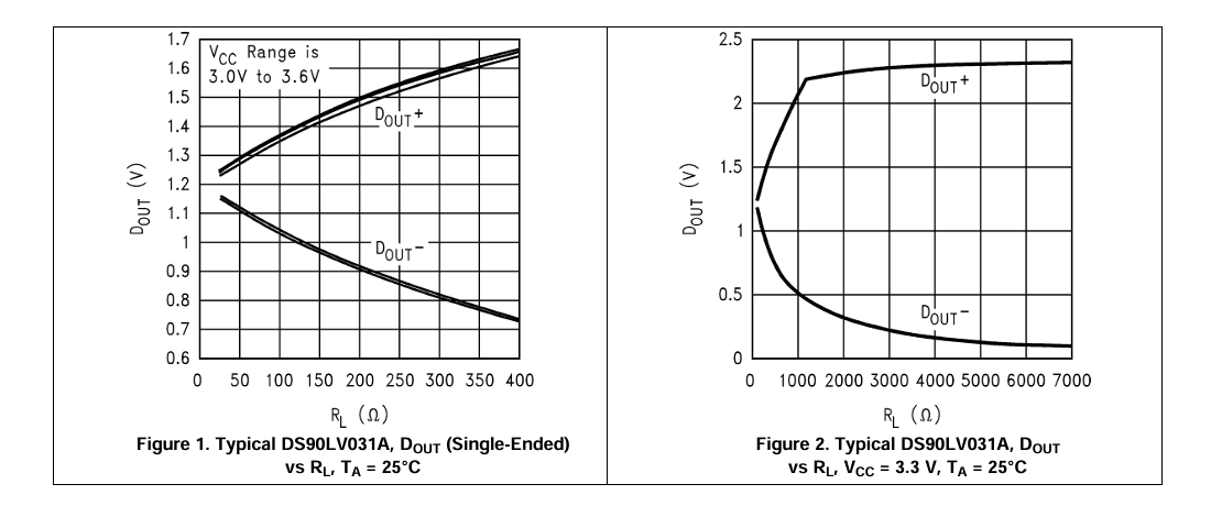
Quote from Pedja on 2 November 2024, 3:21 PMApparently, everyone who tried to connect an LVDS I2S source to S5/S5b A-link input reported this connection to function. Also, by making myself recently an LVDS I2S source for testing purposes, I discovered that most LVDS I2S sources use TI DS90LV031A as a line driver. So, I will try to sum up these facts and experience.
The DS90LV031A driver is a current (and not the usual voltage) signal source, with a typical output swing of 3.5 mA, and the voltage output offset sitting at 1.2 V. Thus, the actual voltage swing at its output is a product of this current, and a receiver's termination resistance, where nominally required value is 100 Ohm. This way, the resulting swing is 350 mV peak-to-peak, around 1.2 V midpoint.
Since A-link does not include a termination resistance, such a source, connected to the A-link input, develops the DS90LV031A "full" output signal voltage swing between 0 V and 2.4 V (or thereabouts).So, at this time, I think it is not very wrong to conclude that the majority of LVDS I2S sources will function with the A-link input, where the signal polarity and channel inversion/delay, as explained previously in this topic (post #5), remain the "only" concern.
For S5b owners, this is good news also because this means that it can operate properly probably with any I2S source with an HDMI connector. Its LVDS I2S input will operate properly with LVDS I2S sources complying with PS Audio pinout, and its A-link input will operate properly not only with A-link sources but also with LVDS I2S sources carrying positive DATA and WS signals at pins 1 and 7, respectively.
Please however note that the opposite does not hold: the A-link (which is a unipolar TTL/CMOS) output i.e. source will not work with LVDS input, at least it will not work with the input employing ubiquitous DS90LV032A line receiver.
Also, because the DS90LV031A driver generally requires the termination at the receiving side, lately shipped S5b units, as opposed to the previous ones, include the 100 Ohm termination resistors at their LVDS I2S input. Initially, as I was suspicious about the (possible) sources' driving capabilities, I was reluctant to include such a termination in the LVDS input, but the current sources, which appear to be the majority here, of course, do not have such a problem.
And, speaking about the termination, the A-link interface is meant as an interface operating in the voltage domain and generally as a real extension of the protocols/signals operating inside the audio equipment, and, for the time being, it will not include the termination.
Apparently, everyone who tried to connect an LVDS I2S source to S5/S5b A-link input reported this connection to function. Also, by making myself recently an LVDS I2S source for testing purposes, I discovered that most LVDS I2S sources use TI DS90LV031A as a line driver. So, I will try to sum up these facts and experience.
The DS90LV031A driver is a current (and not the usual voltage) signal source, with a typical output swing of 3.5 mA, and the voltage output offset sitting at 1.2 V. Thus, the actual voltage swing at its output is a product of this current, and a receiver's termination resistance, where nominally required value is 100 Ohm. This way, the resulting swing is 350 mV peak-to-peak, around 1.2 V midpoint.
Since A-link does not include a termination resistance, such a source, connected to the A-link input, develops the DS90LV031A "full" output signal voltage swing between 0 V and 2.4 V (or thereabouts).
So, at this time, I think it is not very wrong to conclude that the majority of LVDS I2S sources will function with the A-link input, where the signal polarity and channel inversion/delay, as explained previously in this topic (post #5), remain the "only" concern.
For S5b owners, this is good news also because this means that it can operate properly probably with any I2S source with an HDMI connector. Its LVDS I2S input will operate properly with LVDS I2S sources complying with PS Audio pinout, and its A-link input will operate properly not only with A-link sources but also with LVDS I2S sources carrying positive DATA and WS signals at pins 1 and 7, respectively.
Please however note that the opposite does not hold: the A-link (which is a unipolar TTL/CMOS) output i.e. source will not work with LVDS input, at least it will not work with the input employing ubiquitous DS90LV032A line receiver.
Also, because the DS90LV031A driver generally requires the termination at the receiving side, lately shipped S5b units, as opposed to the previous ones, include the 100 Ohm termination resistors at their LVDS I2S input. Initially, as I was suspicious about the (possible) sources' driving capabilities, I was reluctant to include such a termination in the LVDS input, but the current sources, which appear to be the majority here, of course, do not have such a problem.
And, speaking about the termination, the A-link interface is meant as an interface operating in the voltage domain and generally as a real extension of the protocols/signals operating inside the audio equipment, and, for the time being, it will not include the termination.
Quote from sukant on 5 March 2025, 1:01 PM@pedja-rogic
Will Aya 5 work via I2S with Holo Red , also what input do I need to choose to make it work via I2S input.
Will Aya 5 work via I2S with Holo Red , also what input do I need to choose to make it work via I2S input.