A tweak

Quote from Pedja on 8 August 2019, 6:53 PMA few weeks ago I made a significant tweak with the S4 DAC. And, as significant as it is, it is also very simple. Moreover, it requires no parts - it is about the removal of the parts.
And the parts that have to be removed is the pair of capacitors located between the D/A chip and the I/V stage. So, the pair of WIMA caps, marked C403/C503.
The removal brings more natural scale, dynamics, and rhythm, and transparency, and more nice things. And the difference is not about nuances.
So, what these caps are for, in the first place? They are located between the D/A chip output and I/V stage input, to keep the I/V input impedance low across the higher bandwidth, and act as a low pass (more details here), and in some cases also to stabilize the I/V stage. (Please note that you can not use the caps here with the classic opamp I/V, since in that case, it is the opamp inverting input node.) I started using the caps at this point a very long time ago, with different I/V stages, so these caps are inherited. But, once again, the devil is in the details.
I checked this tweak also with the Model S Mk3. It uses the same I/V circuit, but also slightly different parts and layout - and the result was similar. I don't have any original and Mk2 Model S, and Model S USB with me, but the result will be probably the same as with Mk3.
I also tried this tweak with the AYA II / AYA 4 (here these caps are marked C405/C406). The I/V stage here is different, but the tweak was again effective. I would expect the same result with the AYA III too, since it is the same I/V as AYA II and AYA 4.
At this time I am not able to test this with The Model and D-09, again simply because I don't have any sample with me, and at this time I'm not sure if this would be a recommended tweak also for these DACs or not. Even though all my I/V stages topologies during the last 16-17 years were similar, the actual designs of these DACs I/V stages were different.
Caution: Even though it is very simple, this tweak still requires some basic electronics understanding and skills. A DIY people will normally know what to do, but if you lack the skills in this area, please refer to the qualified servicing personnel. Either way, if you have any questions, please contact me for further information, or even better, post your question here, so everyone could benefit.
A few weeks ago I made a significant tweak with the S4 DAC. And, as significant as it is, it is also very simple. Moreover, it requires no parts - it is about the removal of the parts.
And the parts that have to be removed is the pair of capacitors located between the D/A chip and the I/V stage. So, the pair of WIMA caps, marked C403/C503.
The removal brings more natural scale, dynamics, and rhythm, and transparency, and more nice things. And the difference is not about nuances.
So, what these caps are for, in the first place? They are located between the D/A chip output and I/V stage input, to keep the I/V input impedance low across the higher bandwidth, and act as a low pass (more details here), and in some cases also to stabilize the I/V stage. (Please note that you can not use the caps here with the classic opamp I/V, since in that case, it is the opamp inverting input node.) I started using the caps at this point a very long time ago, with different I/V stages, so these caps are inherited. But, once again, the devil is in the details.
I checked this tweak also with the Model S Mk3. It uses the same I/V circuit, but also slightly different parts and layout - and the result was similar. I don't have any original and Mk2 Model S, and Model S USB with me, but the result will be probably the same as with Mk3.
I also tried this tweak with the AYA II / AYA 4 (here these caps are marked C405/C406). The I/V stage here is different, but the tweak was again effective. I would expect the same result with the AYA III too, since it is the same I/V as AYA II and AYA 4.
At this time I am not able to test this with The Model and D-09, again simply because I don't have any sample with me, and at this time I'm not sure if this would be a recommended tweak also for these DACs or not. Even though all my I/V stages topologies during the last 16-17 years were similar, the actual designs of these DACs I/V stages were different.
Caution: Even though it is very simple, this tweak still requires some basic electronics understanding and skills. A DIY people will normally know what to do, but if you lack the skills in this area, please refer to the qualified servicing personnel. Either way, if you have any questions, please contact me for further information, or even better, post your question here, so everyone could benefit.
Quote from Frederick on 15 September 2019, 2:04 PMThanks Pedja...
I will be sending you email soon too regarding the 100pF cap tweak to get a stable 384 kHz stream..
Best regards,
Frederick
Thanks Pedja...
I will be sending you email soon too regarding the 100pF cap tweak to get a stable 384 kHz stream..
Best regards,
Frederick
Quote from Odessa on 12 December 2019, 2:35 PMQuote from Pedja on 08/08/2019, 18:53...I also tried this tweak with the AYA II / AYA 4 (here these caps are marked C405/C406). The I/V stage here is different, but the tweak was again effective. I would expect the same result with the AYA III too, since it is the same I/V as AYA II and AYA 4.
Dear Pedja, to be sure.. those two red caps should be removed. Just short wires instead.. Correct?
Quote from Pedja on 08/08/2019, 18:53...I also tried this tweak with the AYA II / AYA 4 (here these caps are marked C405/C406). The I/V stage here is different, but the tweak was again effective. I would expect the same result with the AYA III too, since it is the same I/V as AYA II and AYA 4.
Dear Pedja, to be sure.. those two red caps should be removed. Just short wires instead.. Correct?
Uploaded files: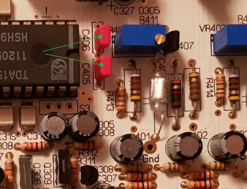
Quote from Pedja on 12 December 2019, 4:07 PMThey only should be removed, and that's all. No wires instead, because these are the shunt caps, and wires here would short the TDA1541A outputs to the ground.
BTW, sometimes these caps can be removed even without pulling the board out of the chassis, by using small cutters or scissors, to cut the caps' leads above the board.
Regards
They only should be removed, and that's all. No wires instead, because these are the shunt caps, and wires here would short the TDA1541A outputs to the ground.
BTW, sometimes these caps can be removed even without pulling the board out of the chassis, by using small cutters or scissors, to cut the caps' leads above the board.
Regards
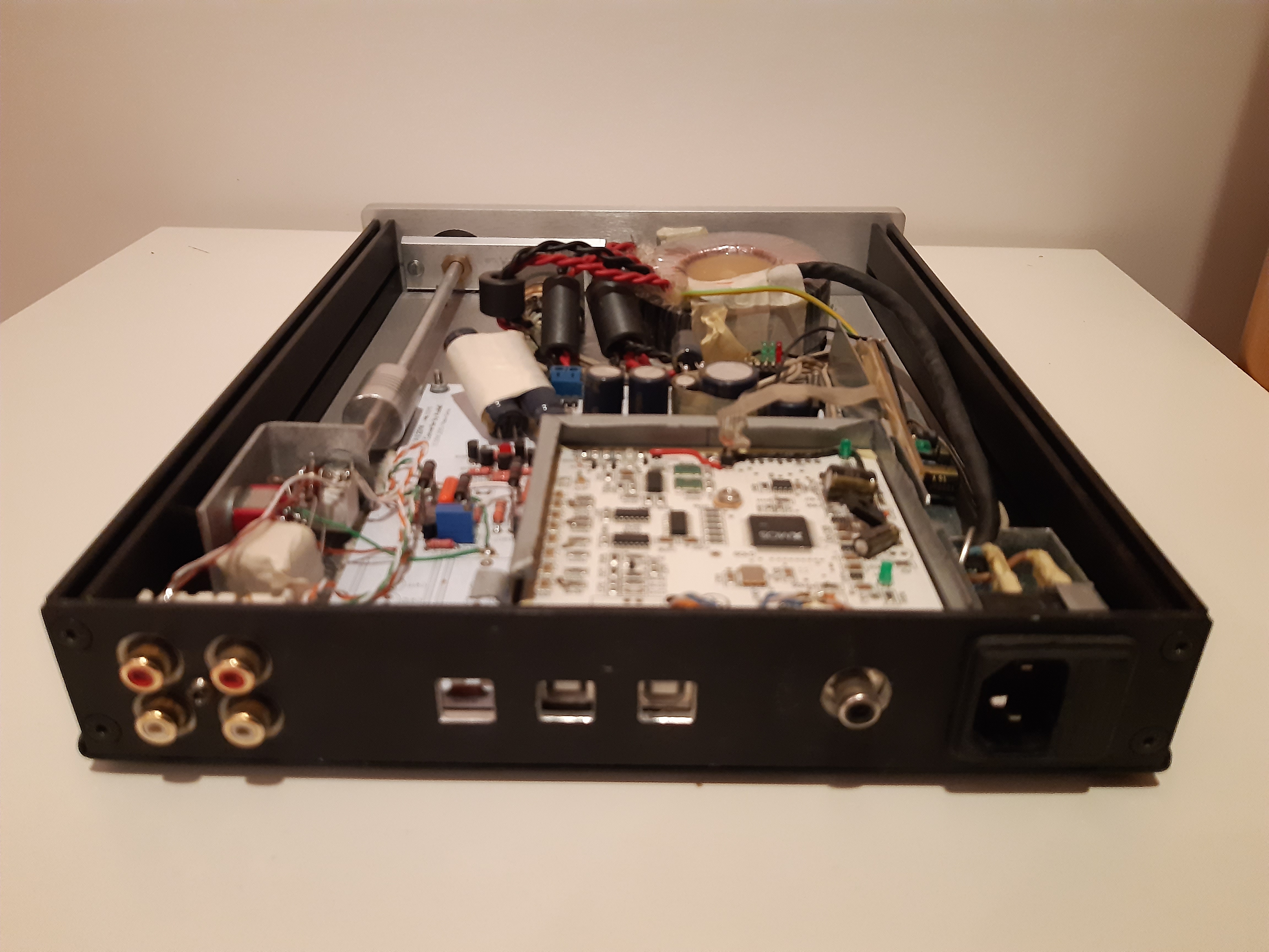
Quote from Berny on 12 May 2020, 5:26 PMI liked the result of this tweak a lot! Unfortunately, I combined it with another modification: I added an RC network for the -15V just after the diode bridge. The idea here was that since the raw voltage (2x9Vac out of my custom Xfo) was more than high enough and I read somewhere this supply was quite critical.. I would first try an additional RC on this supply-line to see the effect.
I combined both as dismanteling my dac is not so easy with the USB part on top in a separate metal case.. and additionally the caps were on the bottom as it where SMDs.After the double mod... sound was bad... I had far too much bass. Later on, it reduced itself together with an overall increase in resolution, very significant in the low end. I suppose the overall gain in resolution and fluidity I get is from the cap removal and the better bass and the temporary bad sound comes from the new cap breaking in... I will certainly try an additional RC on every supply line now! Below a pic of my dac: it has now 3 inputs (original spdif and USB + new USB), all switchable with the input selector (only the used parts get supply, switching when live is a bad idea...).There is also the volume contol, 1K... unfortunately lineair taper (can't find a stereo log 1K cermet, any help is welcome...). On the side is a 3 state toggle switch to disconnect complitly the second output, run it direct or through coupling caps (use it for daily use for now as my amp is dc coupled). I kept the original USB for movies as it is OTG and connects directly on my android movie box... but it is modded to output spdif wich is connected through a miniature relay and matching resistors to the onboard CS8414 (copied from cheap chinese dacs and it works well). Functionality is now how I wanted it, now moving further in the fine tuning.... alle worthy tweaks are welcome! Currently the supply capacitors follow a bit the recommendations from Eldam.Thanks for this very nice dac Pedja! Sorry my post became a bit off topic in the end.
I liked the result of this tweak a lot! Unfortunately, I combined it with another modification: I added an RC network for the -15V just after the diode bridge. The idea here was that since the raw voltage (2x9Vac out of my custom Xfo) was more than high enough and I read somewhere this supply was quite critical.. I would first try an additional RC on this supply-line to see the effect.
Quote from Berny on 12 May 2020, 5:28 PMYes, I don't even have a power switch... 😉
I re-read the first post from Pedja, more dynamic and rythm... indeed!
Yes, I don't even have a power switch... 😉
I re-read the first post from Pedja, more dynamic and rythm... indeed!
Uploaded files:
Quote from Pedja on 12 May 2020, 9:31 PMThanks for your feedback, Berny.
Yes, in these audio things it is certainly better to take one step at a time. RC sections after the bridge can not be bad as such in my experience, but at the end of the day, the unit should be well balanced as a whole.
Power switch removal can be sonically beneficial, but for most users it is not practical.
And speaking about this, a fuse may be actually more critical than a switch. Safety regulations force its use though (for good reasons - if you omit the fuse, neither you nor your unit will be safe). A fuse cap bypass may be used to the rescue, and some time ago I tried experimenting with this - results were good, but you should be cautious and use only low values (the use of mains rated caps is understood), otherwise the safety may again get compromised.
Thanks for your feedback, Berny.
Yes, in these audio things it is certainly better to take one step at a time. RC sections after the bridge can not be bad as such in my experience, but at the end of the day, the unit should be well balanced as a whole.
Power switch removal can be sonically beneficial, but for most users it is not practical.
And speaking about this, a fuse may be actually more critical than a switch. Safety regulations force its use though (for good reasons - if you omit the fuse, neither you nor your unit will be safe). A fuse cap bypass may be used to the rescue, and some time ago I tried experimenting with this - results were good, but you should be cautious and use only low values (the use of mains rated caps is understood), otherwise the safety may again get compromised.
Quote from Berny on 12 May 2020, 11:04 PMWell, it does sound very balanced, it is the bass definition that somehow got totally onto another level.
No worries about safety, fuse is integrated in the iec connector and the case is earth-connected too... about the switch, I use a separate distribution box with isolation transformers (for filtering and balanced supply) for dac, amp and other periferals.. with a general switch and slowstart for the amp.
Well, it does sound very balanced, it is the bass definition that somehow got totally onto another level.
No worries about safety, fuse is integrated in the iec connector and the case is earth-connected too... about the switch, I use a separate distribution box with isolation transformers (for filtering and balanced supply) for dac, amp and other periferals.. with a general switch and slowstart for the amp.
Uploaded files: