First, the “ground“?
The ground is the common reference for a particular device, or devices. Any voltage, be it supply or audio signal, is referenced to it. If we say some point is 5 V DC, or 1 V AC, it is not meant absolutely, but only with respect to some other point. Normally, the reference point is the ground.
When you connect two or more circuits or devices into the audio chain, their grounds get connected, thus making their common reference.
Secondly, a voltage difference (and finite resistance) between some point and the ground makes the current flow. This is one of the most fundamental points to understand the “ground” in electronics: for instance, if we look at the interconnect cable, the signal current flows from a source to an end, however it does not disappear there. Instead, it returns to the source, via a ground path, to make a closed loop. This is why such a ground path is also often referred to as the “return path”. *
Since this ground path is not perfect, but has some resistance, the current flowing there can develop a certain voltage across its ends, thus deteriorating performance. The higher the current and resistance, the higher the error voltage. Moreover, if we have two or more signals sharing the same ground / return path, each of them can develop its own error voltage, and thus mix with other signals.
Now, the “earth“, another term in the mix.
The earth is the third connection available at AC mains sockets. As opposed to the ground, the earth indeed has something to do with soil – it literally provides the connection to the earth, and represents its voltage at a given point. The earth is a very practical means of making safe unit chassis: by connecting the chassis to the earth, and also to the unit ground, any potentially lethal voltage that reaches the chassis will be shorted, thus blowing the safety fuse, and turning the unit off.
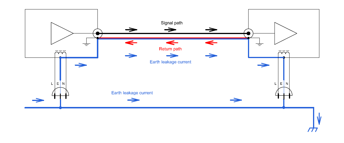
The earth connection however can bring different leakage currents into the system, and this can be a problem if you use more than one connection to the earth, in one system. In such a case, the earth currents can flow through the interconnect ground / return path and, due to a ground conductor resistance, may translate into the error voltage. This can and will deteriorate system performance, and sometimes even produce an audible hum or buzz.
Fig. 1: Classic system with two devices. If both devices use the safety earth,
the earth leakage currents can flow by the signal return path.
This problem can be partially fixed by keeping the mains and interconnect cables short, i.e. their resistance as low as possible. The opposite approach however can work too: some resistance, 10 Ohm or so, can be added to the interconnect ground conductor, to force the earth currents to find the other, lower impedance path(s).
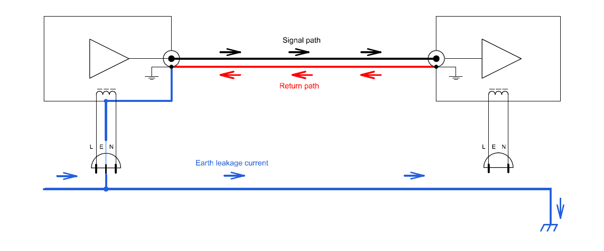
Of course, if only one connection to the safety earth is used, the problem will disappear. Please however note that this should be done in a way that does not compromise safety. The good thing is, many modern audio devices don’t use the safety earth at all, and apply double insulation standards instead, and will not suffer from such problems.
Fig. 2: The system using only one connection to the safety earth.
Earth leakage currents do not flow by signal return path.
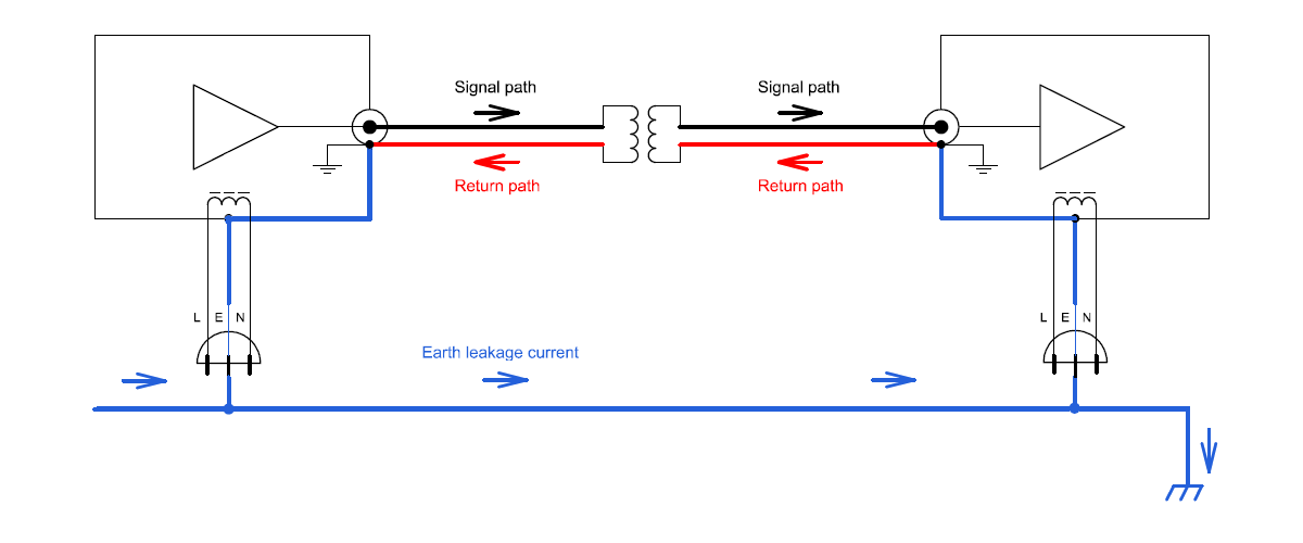
Coupling transformers make a fundamental difference here, because they separate the grounds of two devices. In that way, using the safety earth on both sides is not only tolerable but is also welcome, since the earth will manage the common mode voltage, keeping it low. Practically speaking, in a transformer coupled system, performance is usually better if both sides use the safety earth.
Fig. 3: Transformer coupled system. Both units are connected to the safety earth,
and earth leakage currents do not flow by signal return path.
Audial S4 transformer coupled output measurements are done this way (please see graphs at S4 page), so both the DAC and measurement setup were using the safety earth. This way the noise floor was slightly better than what was achieved by capacitor coupled output (please note the low end). Please also note that the capacitor coupled output performs the shown way only if one side (and not both sides) is using the safety earth.
____________
* – Here I assume “single end” (unbalanced) systems. Balanced topologies and connections are considered advantageous in this regard, because they don’t use the ground as a return path.
Related topic:
Transformer coupling pros and cons (in a nutshell)


Pedja,
thank you for this very valuable article.
In my experience to get the system grounding right is a vital point for sound quality and musicality of an audio system.
As you mentioned the use of more than one connection of the signal ground to the earth in a (non transformer coupled) system can be a problem.
Now in a system where all devices have their chassis grounded to the safety earth with a three wire mains cable there has to be only one connection between the signal ground and chassis ground in order to avoid hum and loss of SQ.
As the grounding of every system is different this one point can be located either in the DAC or the preamp or the poweramp.
Therefore may I suggest that you offer in your upcoming DACs the possibility to lift the signal ground from the chassis ground?
I think this could be done most conveniently with a jumper or a switch inside the case or outside at the back.
Thanks again
Matt
Hello Matt,
Thanks for the input. It is a good idea, and it once might indeed be applied regularly in Audial devices.
Regards