

Everyone trying to find some information on Philips old D/A chips in their documentation is faced from time to time with different, even puzzling data. Probably, it is because different authors were adding different data over time. Inconsistencies however sometimes occur even inside one single paper, and the TDA1541A datasheet is such a paper. The claim of 8x oversampling possibility (in “Features”, page 2), and the 200 kHz stated limit for WS/LE (in “Characteristics”, page 6) is an example of such inconsistency.
For me, when it comes to higher sampling frequencies, a TDA1541(A) limit at the BCK line appeared more important anyhow. Once I tried to send 176.4 kHz by regular I2S (11.2896 MHz BCK) I got unbearable noise, and when I tried a 192 kHz (12.288 MHz BCK), there was no sound at all. So, my conclusion was that the TDA1541A indeed can not work with BCK frequencies above 6.4 MHz (as claimed both in “Quick reference data” and in “Characteristics”). In simultaneous data mode, this 6.4 MHz is however still enough to make it work up to 192 kHz.
Figure 4 in this datasheet was however another puzzle, as it shows the distortion graph taken with a 352.8 kHz sampling frequency. This surely brought some doubts and pointed out that something was still missing, however at that time we practically had no recordings above 192 kHz, and all that simply put me off any further research on the actual TDA1541(A) bandwidth limits.
Recently, I came once again back to this problem, as one of the customers asked for the possibility of making a USB interface for TDA1541(A), that can support 384 kHz. A 384 kHz compatible USB interface is not new anymore, but making it work with TDA1541A is still a challenge. If nothing else, I might conclude that it is not possible.
So finally, is TDA1541(A) 384 kHz compatible? The most definitive answer is yes. Its BCK pin in fact can accept up to 12.288 MHz frequencies, so in simultaneous data mode, it can work up to 384 kHz. What’s fun, I found this only when I tried the old TDA1541 non-A samples of this chip – which worked right from the start. More usual TDA1541A chips again misbehaved, just like they did at 176.4 kHz in I2S. It took me some time to figure out the problem, and detect more misleading data in the -A datasheet at that, and to act accordingly – but finally, they did work too.
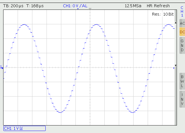
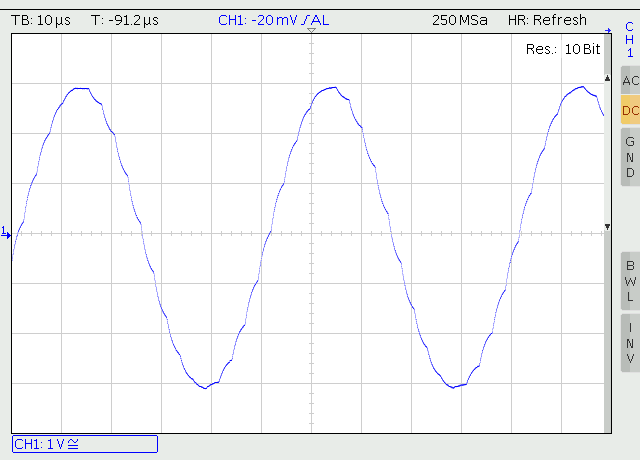
Now, where are we at? The picture below might explain. It shows a 20 kHz sine wave, at 384 kHz Fs, taken from the output of non-oversampling TDA1541A DAC (with negligible 6 dB analog low pass, which -3 dB point is at 130 kHz, so at 20 kHz it is -0.1 dB / -9° phase). And since this is non-o/s, there is no reason to explain that its impulse (square) response is perfect. Those familiar with these topics will know what all this means. Others may look at 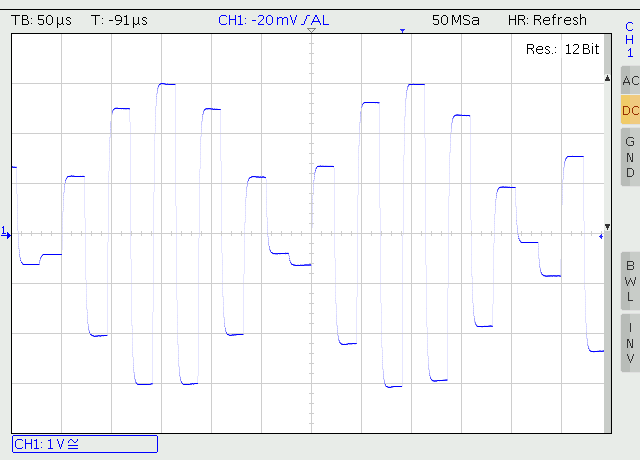
The next step, badly needed here, is on the music industry. Unfortunately, up to now, it has not adopted any higher resolution standard in any significant way.
Hi, great find, where you say:
“Once I tried to send 176.4 kHz by regular I2S (11.2896 MHz BCK), and I got unbearable noise, and when I tried 192 kHz (12.288 MHz BCK) there was no sound at all.”
I noticed the same but thought I was my problem (my XMOS board/wires/earthing/power supply, stupid interconnecting layout). . . and for the n-th time discarded a board. I could not get 176 from a TDA1541 where I had taken the same chip from a Philips board where the SAA7220 DID manage 176 k with ease, so my conclusion (i’m wrong) looked obvious.
You give me inspiration to on with my quest.
Hello Albert,
SAA7220, if I am not mistaken, operates as 16 bit device, so its output is 32 bit I2S frame (16 bit per-channel sub-frame). In that way, TDA1541A can work up to 192 kHz, in I2S. We could make this USB interface 16 bit too, however so long as we seek TDA1541A bandwidth, in my view it is simpler to switch to simultaneous data protocol, and better jitter performance of TDA1541A comes “for free”.
Anyhow, once I might have a look at possibilities of making TDA1541A work up to 192 kHz with 64 bit frame I2S. Its BCK input basically can accept up to 12.288 MHz frequencies, so maybe it is not impossible.
Regards
Pedja,
I have created a simple FPGA-based I2S to PCM converter that would likely allow a TDA1541A to work fine at 384kHz. The bit clock is divided by 4 (64 bit frame into two 16-bit parallel frames) and therefore stays under 7MHz, even at 384kHz.
Hi Matt,
My problem with 16 bit frame was how to define the Latch.
It should be positive going transition to trigger the output, and, according to the datasheet, it should go negative before the first BCK cycle goes positive (and please note that in the sim. data mode the Data is clocked into the register yet on the negative going BCK). With 16 bit frame however the negative going Latch transition inevitably falls into the binary word.
Still, as I found out during my later experiment that made TDA work as 14 bit DAC, the timing shown in the datasheet might not be correct. Also, the minimum time between the negative going Latch and positive going BCK is claimed as 0 ns, which may mean different things.
So, at the end of the day, it might work. Please, keep us updated.
Regards
PS: Yes, I was thinking about 17 or 18 bit frame, but with XMOS it makes a bit of programming fuss.
Pedja,
I time the latch basically as a negative edge triggered signal on the last falling edge of the 16th bit clock that is then gated by the rising edge. That way the latch enable is only high between one half cycle period of the bit clock while the bit clock is low. This is allowed by the internal delays of the latch signal giving 0 setup time and 0 time to next bit clock as specified in the datasheet. Data is transitioned on rising edges of the bit clock so it is stable for every bit clock falling edge and the rising edge of the latch enable.
And now the $1M question:
What does a 384kHz TDA1541A sound like.
Is is as good as a discrete ladder DAC?
Regards,
Johan
PS I have a CD-94II with dual TDA1541A on a separate DAC board which I would like to abuse. 🙂
A TDA1541A playing with 384 kHz source can produce the best sonic results, so far. The problem here is that we don’t have really a lot of such sources. I assume, of course, native hi-res sources, not over- or up-sampled ones.
As for the other DACs, I would expect any other ladder DAC to benefit from higher sampling frequency. That way, it would be fair to compare different DACs only at a given fS.
Regards
I can officially confirm now that the TDA1541A in properly configured Synchronous Data (PCM) mode can do 384kHz just fine. I have built a version of my FPGA-based converter board that uses an AK4137EQ to test the hypothesis. Before, I was only assuming as I didn’t have a source for 384KHz files.
Hello everyone, I can see this is a bit of an old thread, “but” it can’t hurt to throw something out there as to why I found this. I currently have a classic modded Magnavox CDB-650 also known as a “Mod Squad Prism”. It’s currently being repaired by recommendation of SMc Audio (Patrick/Steve) by Ken.
What I would like to try to do, is effectively bypass the transport, and feed what is the known as the digital/main board in this unit that has the TDA1541 on it (that board has been modded, along with a completely new analog board), with a digital COAX, and that way I should be able to pickup/use any streaming device, in my case probably a HEOS Link (LS2). Another way of stating my fantasy is, I would like to use that classic, modded CDB-650 as a DAC, and not just a “CD Player”.
Suggestions?
Hi Pedja
How are you ? Wanna ask a question been a couple of months since I last powered up Aya they other day when I tried playing music all I hear is hum no sound. Where can I check with a dvm.
Was wondering if the output opa is faulty but then again it can’t be for both channels right . Lol
Thks
Hello Jaffrie,
I would start by checking the D/A and output stage supplies. And we will be probably more effective if we move to the email conversation in this case.
Regards
Hello Padja,
I use an upsampling transport (Chord Blu) and soon the Hugo M Scaler that can provide even 705,6khz sampling rates (16×44.1khz).
Now this will be too much but i was thinkin of using a demux and use multiple dac chips to handle this sampling frequency.
What is your thought about this approach?
Best regards,
Frank
Hello Frank,
I have no plans to try to go above 384 kHz with TDA1541A, and I don’t expect the TDA1541A itself would be able to work any way above 384 kHz, either.
The idea with multiple D/A chips looks like a moving average “oversampling” in the analog domain. You can check the old Cambridge CD3, it used something like that, with four TDA1541A, each operating at 176.4 kHz, to achieve 16 times oversampling (IIRC).
Regards
Hello Pedja,
thanks for response !
I do have some Cambridge players to compare but the result is not the same i found.
I guess that is because they still use the original i2s digital filter (SAA7220p).
Now i use 2 stereo dac’s that can handle 2x 176,4 KHz each with great results using dual SPDIF inputs from the transport. The sampling frequency can be changed on the transport and therefore be compared.
Best regards,
Frank
Hi I have a question for this group of fellow enthusiasts. I have a ModSquad Prism player, the Magnavox CDB-650 version, and I somehow have lost the external power supply. Was wondering if anyone could please help me with the voltage/amperage and wiring pinout for the mini XLR connection? It’s driving me crazy not knowing where it went and I figured I’d just build my own or find one compatible.
Any assistance would be very greatly appreciated.
Thanks
Hi, Nick,
Please try to post this request in the diyaudio.com forum.
Best of luck
Hi Frank,
Thank you I will do so. Hopefully I can find the answers I’m looking for.
Hi !
I’m planning to build (again) another TDA1541 DAC, and I have found this site. But I have a double question: Why to build a 384 KHz capable DAC ? and Where can I find music recorded in 384 KHz ?
The advantage of the 352.8/384 kHz sampling rate is beyond doubt for me. Unfortunately, not much has changed in these six years since I wrote the original post. There is still not much music in this format.
2l.no had some free test recordings in different formats, including 352.8 kHz (handy if you want to compare), but it looks like they are currently unavailable.
If you search around, it is best to look for “DXD”.
Hi Pedja,
I don’t believe that higher sampling rate will equals good sound. It’s all in the recording.
This may sound ironic but there is still life in Red Book format. Too bad I can’t share with all what my AyA has become. The other trick is direct I2S to get the best sound but here the transport is very important.
Cheers