


Approaching S6
Quote from Pedja on 16 November 2026, 8:55 AMSo, where did we go from S5b? The space for improvement did not seem huge at first. But as time went on, a few ideas emerged that I decided to develop further.
Most of them were related to the output stage. The I/V stage that I have used since 2008 in all S DACs, as good and unique as it was right from the start, has gradually improved in certain areas over the years. This time, however, I have given it special attention, and the improvements that come with S6 notably bring out more of its qualities. They are both objective, i.e., measurable, and subjective, i.e., audible.
And the overall outcome is, dare I say, a landmark.
But first, about the two main issues that normally appear when attempting to design a highly linear DAC I/V stage. With op-amps, low harmonic distortion is easy to achieve – feedback, as such, yields good numbers. But, as I have stated numerous times, soundwise, it is better if we can do without feedback here. And without it, linearity has to come from the circuit itself.
Yet, as we know, circuits without feedback can also be fairly linear these days, especially at line levels. However, in I/V stages, we face another major issue: the DAC chip output is not only a source – for the I/V stage, it is also a load.
To picture this, you can think of the I/V stage as operating exactly opposite to the usual voltage stages or buffers: the DAC chip is a current source, supposedly of high impedance, whose current flows into (or from) the low-impedance input of the I/V stage. And once the DAC chip and I/V stage are connected this way, the I/V stage must drive the DAC chip output – things here really work kind of "backwards".
The actual circuits may vary, but in principle, a transimpedance I/V stage without feedback looks like this.
The problem mentioned above, which further compromises the linearity of such stages, is that real DAC output impedances are not very high. And their output currents, at such impedances, are often not a sweet spot for small-signal transistors either.
To put this in terms of the TDA1541(A), its output current is 4 mA peak-to-peak, while its output impedance, as I measured it, is 1.65 kΩ. This is the figure I obtained at full signal level using a Taiwan-made HSH9822 sample, and although it may vary with signal level and between different chip series, it is representative enough. Also, full signal level is the most critical condition for characterizing the linearity of a no-feedback I/V stage anyway.
It may also be interesting to note that the TDA1541A output impedance measurement reveals an active, "negative" output impedance. That is, the output current increases as the load impedance, i.e., the voltage developed at the output, increases. For a purely resistive current-source output impedance, we would expect the opposite. However, for current sources using a differential output pair, as the TDA1541(A) does, this is actually expected behaviour.
Going back to the practical level, the key to achieving low distortion is the circuit behind the "I/V circuit" part. And my main method, for about a quarter of a century, has been the use of a diamond transistor structure, in different forms and with varying degrees of success — but the diamond generally offers both good performance and driving capability.
Its implementation in the previous S DACs could keep the third harmonic, which is normally the first indication of overload, at about or below -90 dBFS at full level. The second and several first even-order harmonic levels varied somewhat between samples, contributing to an overall THD figure ranging between 0.002% and 0.006%.
The circuit currently developed for S6 keeps all harmonics below -100 dBFS and brings THD down to 0.001%. And this is a typical figure that, in practice, can sometimes dip just far enough to show three zeros after the decimal point. And yes, once again, this is achieved with the TDA1541A and without global feedback in the output stage.
Details follow.
So, where did we go from S5b? The space for improvement did not seem huge at first. But as time went on, a few ideas emerged that I decided to develop further.
Most of them were related to the output stage. The I/V stage that I have used since 2008 in all S DACs, as good and unique as it was right from the start, has gradually improved in certain areas over the years. This time, however, I have given it special attention, and the improvements that come with S6 notably bring out more of its qualities. They are both objective, i.e., measurable, and subjective, i.e., audible.
And the overall outcome is, dare I say, a landmark.
But first, about the two main issues that normally appear when attempting to design a highly linear DAC I/V stage. With op-amps, low harmonic distortion is easy to achieve – feedback, as such, yields good numbers. But, as I have stated numerous times, soundwise, it is better if we can do without feedback here. And without it, linearity has to come from the circuit itself.
Yet, as we know, circuits without feedback can also be fairly linear these days, especially at line levels. However, in I/V stages, we face another major issue: the DAC chip output is not only a source – for the I/V stage, it is also a load.
To picture this, you can think of the I/V stage as operating exactly opposite to the usual voltage stages or buffers: the DAC chip is a current source, supposedly of high impedance, whose current flows into (or from) the low-impedance input of the I/V stage. And once the DAC chip and I/V stage are connected this way, the I/V stage must drive the DAC chip output – things here really work kind of "backwards".
The actual circuits may vary, but in principle, a transimpedance I/V stage without feedback looks like this.
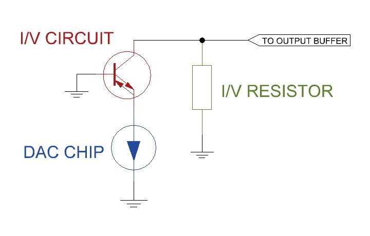
The problem mentioned above, which further compromises the linearity of such stages, is that real DAC output impedances are not very high. And their output currents, at such impedances, are often not a sweet spot for small-signal transistors either.
To put this in terms of the TDA1541(A), its output current is 4 mA peak-to-peak, while its output impedance, as I measured it, is 1.65 kΩ. This is the figure I obtained at full signal level using a Taiwan-made HSH9822 sample, and although it may vary with signal level and between different chip series, it is representative enough. Also, full signal level is the most critical condition for characterizing the linearity of a no-feedback I/V stage anyway.
It may also be interesting to note that the TDA1541A output impedance measurement reveals an active, "negative" output impedance. That is, the output current increases as the load impedance, i.e., the voltage developed at the output, increases. For a purely resistive current-source output impedance, we would expect the opposite. However, for current sources using a differential output pair, as the TDA1541(A) does, this is actually expected behaviour.
Going back to the practical level, the key to achieving low distortion is the circuit behind the "I/V circuit" part. And my main method, for about a quarter of a century, has been the use of a diamond transistor structure, in different forms and with varying degrees of success — but the diamond generally offers both good performance and driving capability.
Its implementation in the previous S DACs could keep the third harmonic, which is normally the first indication of overload, at about or below -90 dBFS at full level. The second and several first even-order harmonic levels varied somewhat between samples, contributing to an overall THD figure ranging between 0.002% and 0.006%.
The circuit currently developed for S6 keeps all harmonics below -100 dBFS and brings THD down to 0.001%. And this is a typical figure that, in practice, can sometimes dip just far enough to show three zeros after the decimal point. And yes, once again, this is achieved with the TDA1541A and without global feedback in the output stage.
Details follow.
Quote from Pedja on 17 November 2026, 1:23 PMIn light of the questions I received after this post, I should clarify that these writings are meant to uncover some of the technical aspects of the latest developments associated with the upcoming S6 DAC. I have been working on it since April, and its release is near. Still, some final decisions are yet to be made, so at this point it is a few weeks away.
However, this topic is not a substitute for the official S6 announcement, which will come soon, together with an introductory offer and the usual details accompanying Audial releases. As always, to stay up to date with such information, I recommend subscribing to the newsletter.
As possibly the most important practical information for now, the targeted regular price of the S6 is €3,500 Ex Works.
The S5b does remain available for the time being.
In light of the questions I received after this post, I should clarify that these writings are meant to uncover some of the technical aspects of the latest developments associated with the upcoming S6 DAC. I have been working on it since April, and its release is near. Still, some final decisions are yet to be made, so at this point it is a few weeks away.
However, this topic is not a substitute for the official S6 announcement, which will come soon, together with an introductory offer and the usual details accompanying Audial releases. As always, to stay up to date with such information, I recommend subscribing to the newsletter.
As possibly the most important practical information for now, the targeted regular price of the S6 is €3,500 Ex Works.
The S5b does remain available for the time being.
Quote from Pedja on 18 November 2026, 9:48 AMSo, let's be as factual as possible. So, the graphs.
The graph below shows the performance of one of the S6 prototype units with my usual Fs = 44.1 kHz TPDF-dithered sine wave signal. With this circuit, I managed to bring the third harmonic well below -100 dBFS, and by trimming the two halves, the second harmonic came in below -100 dBFS as well. The overall THD figure is 0.001%.
Designers working with circuits without feedback know how much their performance can vary from sample to sample, and that is why I am cautious about quoting these figures. Time will provide more data for a reliable statistical assessment of this performance, but for now, in practice, both the second and third harmonics are usually below -105 dBFS. The other harmonics are mostly below -110 dBFS and are actually related to the TDA1541A itself, i.e., to the particular TDA1541A sample being used. So far, the results shown here appear relatively consistent, and the overall THD with dithered signals at Fs = 44.1 kHz falls between 0.0009% and 0.0013%.
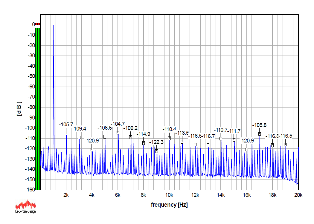
And speaking of the sampling frequency, to tell the story more completely, an interesting characteristic of the TDA1541(A) is that its distortion increases slightly as the sampling frequency increases. The graph below shows the performance of the same S6 device with an Fs = 176.4 kHz signal, using the same dither algorithm, with all else being equal. You will see that some even-order harmonics are higher, mostly the second and the sixth (the fourth is lower, though), and the summed THD at Fs = 176.4 kHz is 0.0014%.
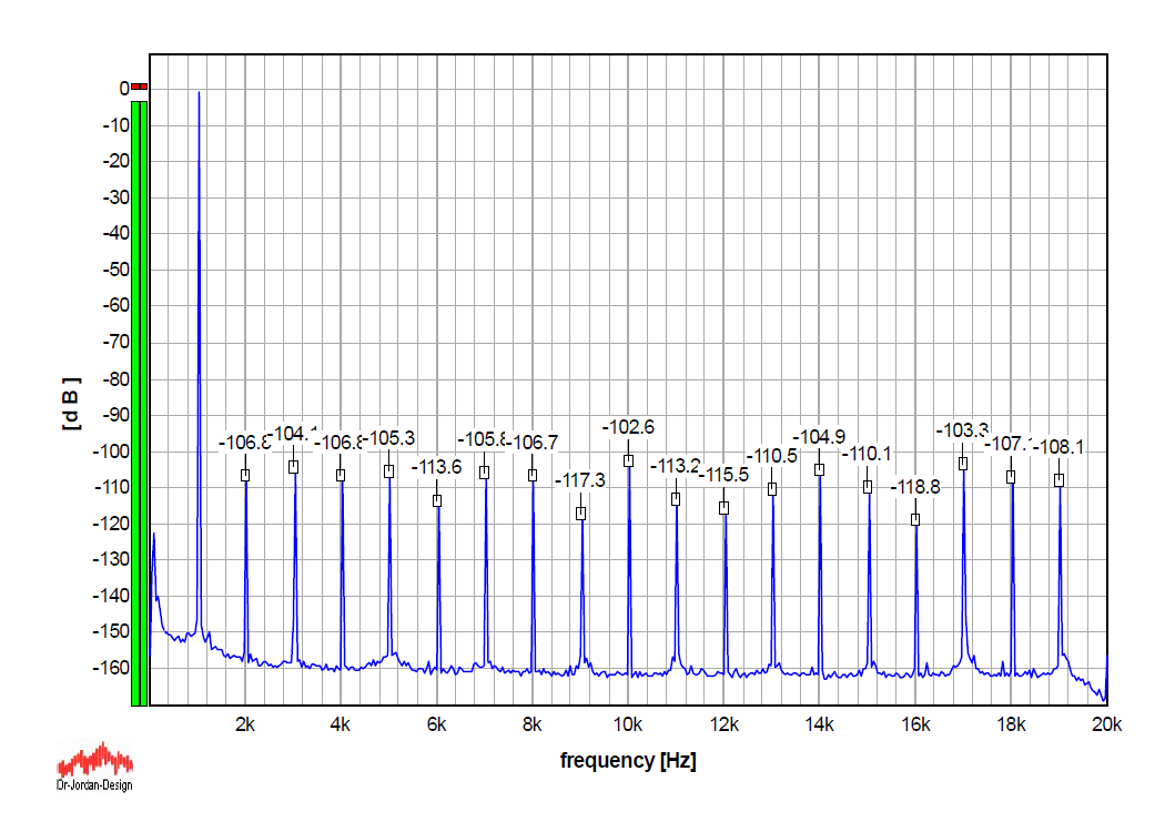
Normally, dithered signals are great for distortion measurements. The price is an increased noise level, and hence such graphs are not representative of the device's noise performance. So, another graph shows the S6 performance with an Fs = 192 kHz undithered sine wave signal, with 1 kHz being an exact submultiple of the sampling frequency. Such a signal normally includes harmonically related artifacts, resulting in a higher overall THD figure of 0.0021%, but avoids any other quantization noise. I also increased the FFT size to one million samples to improve the resolution of my measurement setup.
Yes, the noise floor is down to -160 dBFS, actually hitting the limit of the said (and quite capable) measurement setup. So, the S6 noise, and the TDA1541A for that matter, approaches the noise floor of modern measurement equipment. The only exception is its flicker-noise component, starting below 2 kHz or so, which I might investigate further, but is certainly nothing urgent.
Please also note that this performance is achieved with vintage Allen-Bradley carbon-composition I/V and signal-carrying resistors, so it might be time to reconsider one more traditional myth about their noise.
The only caveat here, and the only thing I am still considering, is the amount of local feedback associated with emitter degeneration in the circuit I use. It is not an aggressive kind of feedback, not even within the realm of local feedback mechanisms, but I am still considering reducing it anyhow. So, if I find this sonically beneficial, the final distortion figure may be only a tiny bit higher.
So, let's be as factual as possible. So, the graphs.
The graph below shows the performance of one of the S6 prototype units with my usual Fs = 44.1 kHz TPDF-dithered sine wave signal. With this circuit, I managed to bring the third harmonic well below -100 dBFS, and by trimming the two halves, the second harmonic came in below -100 dBFS as well. The overall THD figure is 0.001%.
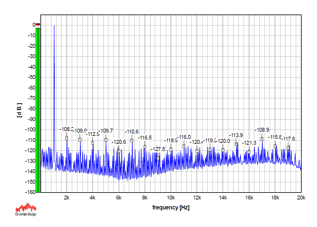
Designers working with circuits without feedback know how much their performance can vary from sample to sample, and that is why I am cautious about quoting these figures. Time will provide more data for a reliable statistical assessment of this performance, but for now, in practice, both the second and third harmonics are usually below -105 dBFS. The other harmonics are mostly below -110 dBFS and are actually related to the TDA1541A itself, i.e., to the particular TDA1541A sample being used. So far, the results shown here appear relatively consistent, and the overall THD with dithered signals at Fs = 44.1 kHz falls between 0.0009% and 0.0013%.
And speaking of the sampling frequency, to tell the story more completely, an interesting characteristic of the TDA1541(A) is that its distortion increases slightly as the sampling frequency increases. The graph below shows the performance of the same S6 device with an Fs = 176.4 kHz signal, using the same dither algorithm, with all else being equal. You will see that some even-order harmonics are higher, mostly the second and the sixth (the fourth is lower, though), and the summed THD at Fs = 176.4 kHz is 0.0014%.
Normally, dithered signals are great for distortion measurements. The price is an increased noise level, and hence such graphs are not representative of the device's noise performance. So, another graph shows the S6 performance with an Fs = 192 kHz undithered sine wave signal, with 1 kHz being an exact submultiple of the sampling frequency. Such a signal normally includes harmonically related artifacts, resulting in a higher overall THD figure of 0.0021%, but avoids any other quantization noise. I also increased the FFT size to one million samples to improve the resolution of my measurement setup.
Yes, the noise floor is down to -160 dBFS, actually hitting the limit of the said (and quite capable) measurement setup. So, the S6 noise, and the TDA1541A for that matter, approaches the noise floor of modern measurement equipment. The only exception is its flicker-noise component, starting below 2 kHz or so, which I might investigate further, but is certainly nothing urgent.
Please also note that this performance is achieved with vintage Allen-Bradley carbon-composition I/V and signal-carrying resistors, so it might be time to reconsider one more traditional myth about their noise.
The only caveat here, and the only thing I am still considering, is the amount of local feedback associated with emitter degeneration in the circuit I use. It is not an aggressive kind of feedback, not even within the realm of local feedback mechanisms, but I am still considering reducing it anyhow. So, if I find this sonically beneficial, the final distortion figure may be only a tiny bit higher.