

AYA 5 I/V stage bias, performance and thermal issues

Quote from Pedja on 23 March 2022, 12:55 PMAs promised in the e-mail sent to the AYA 5 users, here are more details on the performance of the AYA 5 I/V stage in its latest iteration, with the bias set by 4k7, as explained in the assembly manual revision C. Namely, I am posting the performance of my prototype unit, and you might compare it to its original performance, posted in October to the original AYA 5 page.
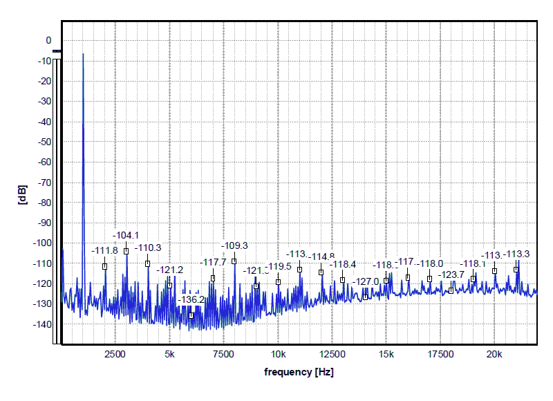
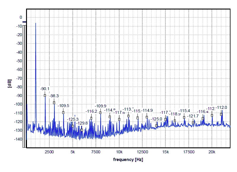
So, the one channel, THD is 0.0021%. Remember, with 3k3 bias, the THD was 0.007%.
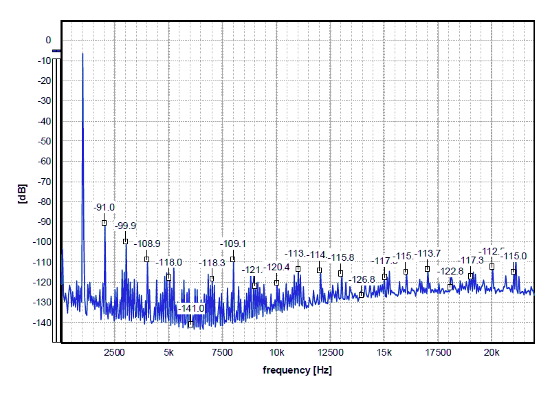
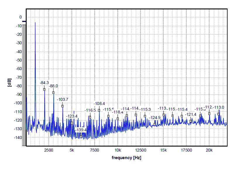
And the other channel, THD is 0.0066%. With 3k3 bias, the THD was 0.015%.
And when you consider the level of the third harmonic of the original setup, you might understand why I was reluctant to decrease the bias current. Usually, the third harmonic (or generally odd-order components) point out the circuit approaching its driving capabilities (i.e. the sine waveform approaching the square wave). And the stage driving capabilities normally decrease as its bias current decreases (and vice versa). And, to understand the way the I/V stage operates, you have to think the opposite way of usual voltage amplifiers set up - it is the input of the I/V stage that has to "drive" the output of the D/A chip, i.e. its output current and impedance. Besides, with a lower bias current, the I/V input impedance would increase.
However, the thermal issues triggered this step - and it turned out to be successful in both regards. I still have to think about all the reasons behind this better performance with lower bias current, but for now, there is no reason not to just take this advantage like that.
Sonically speaking, with this lower bias, the I/V stage is more smooth, more dynamic, and more natural. Taking into account this is "only" about the I/V stage bias, set by four cheap resistors, it is hard to ask for more. And, despite its somewhat higher input impedance (now it is nominally 4.5 Ohm, as opposed to the previous 3.5 Ohm), I can not report any sonic shortcomings.
Also, this may be the moment to once again address publicly the questions about transistors matching requirements. When you look at these two graphs, you will notice the second harmonic varying for about 20 dB (and most of the other components relatively stable). This is where the matching between the NPN and PNP parts may help. This is however usually a tricky task, and although your mileage may vary, for me these levels are anyhow satisfyingly low, and actual sonic gains may be small.
As promised in the e-mail sent to the AYA 5 users, here are more details on the performance of the AYA 5 I/V stage in its latest iteration, with the bias set by 4k7, as explained in the assembly manual revision C. Namely, I am posting the performance of my prototype unit, and you might compare it to its original performance, posted in October to the original AYA 5 page.
So, the one channel, THD is 0.0021%. Remember, with 3k3 bias, the THD was 0.007%.
And the other channel, THD is 0.0066%. With 3k3 bias, the THD was 0.015%.
And when you consider the level of the third harmonic of the original setup, you might understand why I was reluctant to decrease the bias current. Usually, the third harmonic (or generally odd-order components) point out the circuit approaching its driving capabilities (i.e. the sine waveform approaching the square wave). And the stage driving capabilities normally decrease as its bias current decreases (and vice versa). And, to understand the way the I/V stage operates, you have to think the opposite way of usual voltage amplifiers set up - it is the input of the I/V stage that has to "drive" the output of the D/A chip, i.e. its output current and impedance. Besides, with a lower bias current, the I/V input impedance would increase.
However, the thermal issues triggered this step - and it turned out to be successful in both regards. I still have to think about all the reasons behind this better performance with lower bias current, but for now, there is no reason not to just take this advantage like that.
Sonically speaking, with this lower bias, the I/V stage is more smooth, more dynamic, and more natural. Taking into account this is "only" about the I/V stage bias, set by four cheap resistors, it is hard to ask for more. And, despite its somewhat higher input impedance (now it is nominally 4.5 Ohm, as opposed to the previous 3.5 Ohm), I can not report any sonic shortcomings.
Also, this may be the moment to once again address publicly the questions about transistors matching requirements. When you look at these two graphs, you will notice the second harmonic varying for about 20 dB (and most of the other components relatively stable). This is where the matching between the NPN and PNP parts may help. This is however usually a tricky task, and although your mileage may vary, for me these levels are anyhow satisfyingly low, and actual sonic gains may be small.
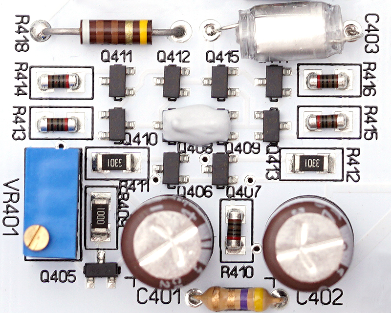
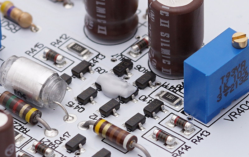
Quote from Pedja on 13 April 2022, 11:11 PMAs for the thermal paste applied to the Q408/Q409 and Q508/Q509, here is what it looks like. And if you are wondering about the way it influences the audio performance, the effects are not that significant and are not really audible, but they can be visible on the spectral analyzer, as slightly increased second and reduced third harmonic. Namely, with and without paste, they may differ for up to about 2 dB. (I guess there is no need to post the graphs showing this difference.)
Anyway, the paste also keeps the bias of the emitter and collector string of the diamond structure under control, and it should be efficient enough also with 3k3 bias resistors. At least that was my experience using Thermal Grizzly Kryonaut with several otherwise thermally critical AYA 5 output stages.
Generally, with either this thermal paste at these transistors or 4k7 bias, I did not experience thermal runaway. With both, I would say the thermal runaway is impossible.
Although I was using diamond stages for decades, with AYA 5 I/V I learned how SOT parts require a somewhat different approach to the thermal issues. As it is already explained in the AYA 5 assembly manual, due to Vbe mismatching, it is possible to experience thermal runaway at transistors Q408/Q409 and Q508/Q509. While, due to the current limited supply, this runaway is not self-destructive, it certainly makes the I/V stage not perform as supposed.
As for the thermal paste applied to the Q408/Q409 and Q508/Q509, here is what it looks like. And if you are wondering about the way it influences the audio performance, the effects are not that significant and are not really audible, but they can be visible on the spectral analyzer, as slightly increased second and reduced third harmonic. Namely, with and without paste, they may differ for up to about 2 dB. (I guess there is no need to post the graphs showing this difference.)
Anyway, the paste also keeps the bias of the emitter and collector string of the diamond structure under control, and it should be efficient enough also with 3k3 bias resistors. At least that was my experience using Thermal Grizzly Kryonaut with several otherwise thermally critical AYA 5 output stages.
Generally, with either this thermal paste at these transistors or 4k7 bias, I did not experience thermal runaway. With both, I would say the thermal runaway is impossible.
Although I was using diamond stages for decades, with AYA 5 I/V I learned how SOT parts require a somewhat different approach to the thermal issues. As it is already explained in the AYA 5 assembly manual, due to Vbe mismatching, it is possible to experience thermal runaway at transistors Q408/Q409 and Q508/Q509. While, due to the current limited supply, this runaway is not self-destructive, it certainly makes the I/V stage not perform as supposed.
Uploaded files:
Quote from Pedja on 12 June 2022, 5:05 PMA few more words on why I have recommended Thermal Grizzly Kryonaut.
Usually, the thermal conductivity of materials is tightly associated with their electrical conductivity. For instance, when you look at the properties of metals, copper conductivity is better both electrically and thermally than aluminum conductivity, and it is almost twice better in both respects. And silver is about 5% better than copper, both electrically and thermally.
On the other side, the materials we use as electrical isolators (polymers, mica, etc), are usually good thermal isolators too.
In this case, we have the opposite requirements for the thermal paste, as we need the material that is not electrically conductive but with good thermal conductivity.
Hence the thermal paste must be the material that is not electrically conductive in the first place, but with a maximum thermal conductivity at that. Thermal pastes or insulation pads we use for the electronics have thermal conductivity between 1 and 3 W/(m.K) (Watts per meter-Kelvin). Thermal Grizzly Kryonaut thermal conductivity is 12.5 W/(m.K). This figure still might not look that great when you compare it, for instance, to the thermal conductivity of copper, which is 400 W/(m.K), but it is about the best you will find for electrically non-conductive material.
This feature, in my view, justifies its relatively high price, and so long as you need a couple of drops, the price should be actually acceptable. However, beware of fakes. I would recommend buying this paste exclusively at authorized sellers, and you will find the list on the Thermal Grizzly website.
https://www.thermal-grizzly.com/en/where-to-buy
Also, some of you asked how to remove the paste if needed. It is quite simple to do that, firstly by removing most of it mechanically and then cleaning the residues with alcohol. I use 96% ethanol, but a more conventional 75% should do too.
A few more words on why I have recommended Thermal Grizzly Kryonaut.
Usually, the thermal conductivity of materials is tightly associated with their electrical conductivity. For instance, when you look at the properties of metals, copper conductivity is better both electrically and thermally than aluminum conductivity, and it is almost twice better in both respects. And silver is about 5% better than copper, both electrically and thermally.
On the other side, the materials we use as electrical isolators (polymers, mica, etc), are usually good thermal isolators too.
In this case, we have the opposite requirements for the thermal paste, as we need the material that is not electrically conductive but with good thermal conductivity.
Hence the thermal paste must be the material that is not electrically conductive in the first place, but with a maximum thermal conductivity at that. Thermal pastes or insulation pads we use for the electronics have thermal conductivity between 1 and 3 W/(m.K) (Watts per meter-Kelvin). Thermal Grizzly Kryonaut thermal conductivity is 12.5 W/(m.K). This figure still might not look that great when you compare it, for instance, to the thermal conductivity of copper, which is 400 W/(m.K), but it is about the best you will find for electrically non-conductive material.
This feature, in my view, justifies its relatively high price, and so long as you need a couple of drops, the price should be actually acceptable. However, beware of fakes. I would recommend buying this paste exclusively at authorized sellers, and you will find the list on the Thermal Grizzly website.
https://www.thermal-grizzly.com/en/where-to-buy
Also, some of you asked how to remove the paste if needed. It is quite simple to do that, firstly by removing most of it mechanically and then cleaning the residues with alcohol. I use 96% ethanol, but a more conventional 75% should do too.