


Balanced, symmetric, or differential DAC — anyhow, is it worth it? The PCM1704K case.

Quote from Pedja on 14 October 2026, 9:29 AMOne topic that normally draws the attention of sound devotees is the benefit of so-called balanced topologies. Within this term, "balanced", several different phenomena are, however, often lumped together — phenomena that are closely related, but not really the same.
So, let's do a kind of intro.
Historically, the term balanced comes from the high-frequency transmission world, and it was originally associated with techniques meant to improve noise rejection over long distances. If we use two wires instead of one, the noise picked up by the line will be largely the same on both, and, being common to both wires, it can be rejected when the difference between them is taken. Clever and convenient.
And although most of us, thinking about balanced lines, also assume two out-of-phase, symmetric signals, the signals on the two wires can actually be anything. For today's audiophiles, it may be interesting to note that the term balanced originally did not refer to the source signal(s), but to the line impedances. The important point was that the two conductors presented equal impedances to ground and to the surrounding environment, while maintaining the required transmission-line impedance. This preserves the waveform and makes externally induced noise appear equally on both conductors, allowing it to be rejected as common-mode noise. That is what "balanced" was meant to mean.
Still, regarding the signals on the two wires, although they can indeed be anything, in practice they were generally assumed to be symmetric. This is because this way the differential signal, and thus the common-mode rejection ratio, is maximized.
And there are basically two ways to provide such a symmetric signal on the source side: transformer coupling at the output, or a truly symmetric circuit.
Transformer output coupling can generally provide a floating output (as in all Audial S DACs), so the ground reference is defined at the receiving end (amplifier), where equal impedances to ground establish the symmetry required for common-mode rejection.
The other option is to duplicate the source circuit and generate an inverted signal in the added half. Another step in this direction involves some form of cross-coupling between the two poles, so that the two sides are interdependent and a symmetric output is maintained regardless of whether the input signal itself is symmetric. This cross-coupling can be more or less effective, but sometimes, as we will see later, it is not possible at all.
Regardless, such a doubled architecture brings a few more possible benefits. One is the cancellation of even-order distortion (as some may know, balancing two sides of a push-pull architecture also cancels even-order distortion), and the other, since the effective differential peak level gets twice as high with respect to the noise floor, is an increase in signal-to-noise ratio, by 3 to 6 dB, depending on the nature of the noise.
So, for now, there are three possible benefits to summarize. The first two are achievable by transformer coupling, while the third is limited to active symmetric circuits.
1. Improved interconnection noise rejection
2. Improved, i.e., simplified system grounding
3. Lower even-order distortion and 3–6 dB higher SNRThe next part will refer to the associated DAC architectures.
One topic that normally draws the attention of sound devotees is the benefit of so-called balanced topologies. Within this term, "balanced", several different phenomena are, however, often lumped together — phenomena that are closely related, but not really the same.
So, let's do a kind of intro.
Historically, the term balanced comes from the high-frequency transmission world, and it was originally associated with techniques meant to improve noise rejection over long distances. If we use two wires instead of one, the noise picked up by the line will be largely the same on both, and, being common to both wires, it can be rejected when the difference between them is taken. Clever and convenient.
And although most of us, thinking about balanced lines, also assume two out-of-phase, symmetric signals, the signals on the two wires can actually be anything. For today's audiophiles, it may be interesting to note that the term balanced originally did not refer to the source signal(s), but to the line impedances. The important point was that the two conductors presented equal impedances to ground and to the surrounding environment, while maintaining the required transmission-line impedance. This preserves the waveform and makes externally induced noise appear equally on both conductors, allowing it to be rejected as common-mode noise. That is what "balanced" was meant to mean.
Still, regarding the signals on the two wires, although they can indeed be anything, in practice they were generally assumed to be symmetric. This is because this way the differential signal, and thus the common-mode rejection ratio, is maximized.
And there are basically two ways to provide such a symmetric signal on the source side: transformer coupling at the output, or a truly symmetric circuit.
Transformer output coupling can generally provide a floating output (as in all Audial S DACs), so the ground reference is defined at the receiving end (amplifier), where equal impedances to ground establish the symmetry required for common-mode rejection.
The other option is to duplicate the source circuit and generate an inverted signal in the added half. Another step in this direction involves some form of cross-coupling between the two poles, so that the two sides are interdependent and a symmetric output is maintained regardless of whether the input signal itself is symmetric. This cross-coupling can be more or less effective, but sometimes, as we will see later, it is not possible at all.
Regardless, such a doubled architecture brings a few more possible benefits. One is the cancellation of even-order distortion (as some may know, balancing two sides of a push-pull architecture also cancels even-order distortion), and the other, since the effective differential peak level gets twice as high with respect to the noise floor, is an increase in signal-to-noise ratio, by 3 to 6 dB, depending on the nature of the noise.
So, for now, there are three possible benefits to summarize. The first two are achievable by transformer coupling, while the third is limited to active symmetric circuits.
1. Improved interconnection noise rejection
2. Improved, i.e., simplified system grounding
3. Lower even-order distortion and 3–6 dB higher SNR
The next part will refer to the associated DAC architectures.
Quote from Pedja on 15 October 2026, 10:29 AMSo, the birthplace of balanced architecture was in transmission lines, i.e., interfaces, but let's look more closely at the phenomena related to the devices themselves. Or, more particularly, at the possible benefits such an architecture brings to DACs.
Other devices may have specific benefits of their own. Power amplifiers are one example, and the Audial A21 is such an amplifier. By driving the loudspeakers with a symmetric signal, the available power increases fourfold, while the supply voltage remains the same. This makes it possible to design power amplifiers with respectable power, yet keep their operating points in the sonically best range.
Also, speaking on a general level, some may recall that symmetrical circuits are also more supply-friendly, since each half draws the same current in the opposite direction, in sum representing a nearly constant load. But I will put all such things aside for now.
Now, for DACs. As said, the Audial S/S4/S5 transformer coupling provides a floating output, and thus the interface can be balanced. This can improve the common-mode rejection of the interface, as well as system grounding, but the performance of the DAC as such, putting the performance of the transformer itself (distortion, bandwidth) aside, remains the same.
Other than this option, the whole DAC topology can be symmetric. Or "balanced". When it comes to the devices themselves, both these terms, apart from their original meaning related to the interface as explained above, probably carry more mundane connotations. Symmetric probably connotes two simply out-of-phase signals, but also that they are exactly of the same magnitude. And balanced would mean that "the action on one side produces a reaction on the other". Say, if inputs fed with +1 V and -1 V produce +1 V and -1 V at the outputs, then if the inputs are fed with +2 V and 0 V, and if the circuit balances the signals, it should again output +1 V and -1 V. So, for any difference between the inputs, the outputs remain centered around a common reference. And to perform such balancing, some form of cross-coupling between the two sides is necessary.
Most often, such DAC topologies are implemented using DAC chips that already provide symmetric outputs. And DAC chips often do have a differential transistor pair as their output stage, and thus some form of cross-coupling between the positive and negative outputs. The actual internal circuits, and thus the actual "balancing action", however, usually remain hidden and unknown. Less often, two DAC chip sections are used per channel, one providing the positive and the other the negative output. In this case, the two poles are normally not cross-coupled.
Either way, the DAC chips outputs are usually fed into two fully separate I/V sections per channel, and then their outputs, buffered or not, are sent to XLR connectors. More recently, particularly with OPA1632 or similar differential op-amp-based I/V stages, the two poles are sometimes cross-coupled there as well.
With no-feedback I/V circuits, balancing in terms of cross-coupling is not normally possible. This is because balancing circuits practically have to use emitter nodes to couple the two sides and mirror their currents, while in no-feedback I/V stages those emitter nodes must serve as inputs. That said, some very specific circuits could probably still be designed for such a purpose, but they would be highly specialized, and to my knowledge none has ever taken that route.
So, looking at all this, you might note several different scenarios. In practice, you will also find that only a tiny fraction of all DAC units use such cross-coupling between the two poles, especially if you want it at every stage. On the other hand, the terms balanced, and especially truly balanced, fully balanced, or fully symmetric, are too often used as marketing terms that do not really tell us much about the actual design.
Generally, every symmetric circuit, whether it is cross-coupled or not, is able to lower even-order distortion. But the better the symmetry between the two signals, the better this cancellation will be.
Although this principle is well understood, direct measurements comparing symmetric circuits whose two halves operate independently with cross-coupled ones, and quantifying the resulting cancellation of even-order distortion, remain surprisingly scarce. According to David Rich's simulations, starting with two amplifiers with 2% second harmonic distortion, their perfectly balanced configuration can cancel it completely, while mismatches between the amplifiers of 1% and 5% reduce it 100 and 40 times, respectively.
The story of PCM1704K follows.
So, the birthplace of balanced architecture was in transmission lines, i.e., interfaces, but let's look more closely at the phenomena related to the devices themselves. Or, more particularly, at the possible benefits such an architecture brings to DACs.
Other devices may have specific benefits of their own. Power amplifiers are one example, and the Audial A21 is such an amplifier. By driving the loudspeakers with a symmetric signal, the available power increases fourfold, while the supply voltage remains the same. This makes it possible to design power amplifiers with respectable power, yet keep their operating points in the sonically best range.
Also, speaking on a general level, some may recall that symmetrical circuits are also more supply-friendly, since each half draws the same current in the opposite direction, in sum representing a nearly constant load. But I will put all such things aside for now.
Now, for DACs. As said, the Audial S/S4/S5 transformer coupling provides a floating output, and thus the interface can be balanced. This can improve the common-mode rejection of the interface, as well as system grounding, but the performance of the DAC as such, putting the performance of the transformer itself (distortion, bandwidth) aside, remains the same.
Other than this option, the whole DAC topology can be symmetric. Or "balanced". When it comes to the devices themselves, both these terms, apart from their original meaning related to the interface as explained above, probably carry more mundane connotations. Symmetric probably connotes two simply out-of-phase signals, but also that they are exactly of the same magnitude. And balanced would mean that "the action on one side produces a reaction on the other". Say, if inputs fed with +1 V and -1 V produce +1 V and -1 V at the outputs, then if the inputs are fed with +2 V and 0 V, and if the circuit balances the signals, it should again output +1 V and -1 V. So, for any difference between the inputs, the outputs remain centered around a common reference. And to perform such balancing, some form of cross-coupling between the two sides is necessary.
Most often, such DAC topologies are implemented using DAC chips that already provide symmetric outputs. And DAC chips often do have a differential transistor pair as their output stage, and thus some form of cross-coupling between the positive and negative outputs. The actual internal circuits, and thus the actual "balancing action", however, usually remain hidden and unknown. Less often, two DAC chip sections are used per channel, one providing the positive and the other the negative output. In this case, the two poles are normally not cross-coupled.
Either way, the DAC chips outputs are usually fed into two fully separate I/V sections per channel, and then their outputs, buffered or not, are sent to XLR connectors. More recently, particularly with OPA1632 or similar differential op-amp-based I/V stages, the two poles are sometimes cross-coupled there as well.
With no-feedback I/V circuits, balancing in terms of cross-coupling is not normally possible. This is because balancing circuits practically have to use emitter nodes to couple the two sides and mirror their currents, while in no-feedback I/V stages those emitter nodes must serve as inputs. That said, some very specific circuits could probably still be designed for such a purpose, but they would be highly specialized, and to my knowledge none has ever taken that route.
So, looking at all this, you might note several different scenarios. In practice, you will also find that only a tiny fraction of all DAC units use such cross-coupling between the two poles, especially if you want it at every stage. On the other hand, the terms balanced, and especially truly balanced, fully balanced, or fully symmetric, are too often used as marketing terms that do not really tell us much about the actual design.
Generally, every symmetric circuit, whether it is cross-coupled or not, is able to lower even-order distortion. But the better the symmetry between the two signals, the better this cancellation will be.
Although this principle is well understood, direct measurements comparing symmetric circuits whose two halves operate independently with cross-coupled ones, and quantifying the resulting cancellation of even-order distortion, remain surprisingly scarce. According to David Rich's simulations, starting with two amplifiers with 2% second harmonic distortion, their perfectly balanced configuration can cancel it completely, while mismatches between the amplifiers of 1% and 5% reduce it 100 and 40 times, respectively.
The story of PCM1704K follows.
Quote from Pedja on 18 October 2026, 6:50 PMBack in 2010, I designed the world's first high-resolution (24-bit/192 kHz) non-oversampling USB DAC for Gramofone UK. The brand is now defunct, but from today's perspective, it is clear that this design was significantly ahead of its time.
In the meantime, I haven't had much interest in producing DACs with the PCM1704K. This chip is great, but soon after that project it was discontinued, just as the TDA1541A had been more than a decade earlier, and I simply did not like the additional problems with availability.
Last year, however, I was approached by a customer who wanted me to revisit that design. In addition, he wanted a differential XLR output with no coupling transformers. So, a kind of symmetric design with two PCM1704K chips per channel. With a bit more experience and knowledge gained over the years, some more ideas, and the freedom to realize them, the project sounded good, so I accepted.
And so the project was done. With USB, LVDS I2S, and A-link (1704 format) inputs, all working up to 384 kHz. The D/A section uses two PCM1704K chips per channel, each providing one pole of the (purportedly) symmetric output, normally with no cross-coupling, and two I/V stages per channel, each operating separately on its respective pole. The I/V stage circuit is similar to that used in the S5b (and the old Gramofone GF02 DAC), with some changes to avoid or minimize even local feedback paths, as well as some adjustments and the possibility of trimming the upper and lower halves to minimize even-order distortion even at the unbalanced output. The outputs are both RCA and XLR, with the RCA output simply carrying the positive half.
Now, enough talk. What you probably really want to know here is how these two options compare. And here is the graph showing the performance of the RCA output (red curve) and the XLR output (blue curve). I used an undithered 1 kHz sine wave, 24-bit, at Fs = 192 kHz. Both curves are scaled to 0 dBFS, which is 2.2 V RMS for RCA and 4.4 V RMS for XLR.
In practice, due to the lack of feedback in the output stage and the R2R DAC architecture, each harmonic may vary by anything from a couple of dB to ten dB, some going down and some going up, but what you see here is a relatively representative case. As expected, the XLR output shows lower levels of even-order components, resulting in a slightly better overall THD figure of 0.0015% versus 0.0017% for RCA.
Several lower-order components are dominated by the output stage, but as everything is actually close to the limits of the DAC chips, you also see some "stubborn" higher-order components. Unlike in no-feedback analog circuits, their levels do not generally fall off with harmonic order, which indicates that they originate mainly in the converter chips rather than in the analog output stage. Also, as a side note, I may add that the graph, with the blue XLR curve on top, hides a somewhat interesting fact: the third and especially the fifth harmonic may sometimes be a few dB higher at the XLR output (something to think about later).
Both outputs show extremely low wideband noise. The visible difference in favour of XLR is probably actually larger, with about 6 dB expected here, but at -160 dB I am already at the limit of the measurement setup.
The bottom end of the audio spectrum, where the mains frequency and the dominant portion of ground-loop spurious signals also usually show up, also indicates the advantage of the XLR connection. I paid particular attention to the grounding of the measurement system, and although at my best I can achieve figures about 10 dB better for RCA and 20 dB better for XLR, both figures shown here are low (please note that -120 dB corresponds to 2.2 µV for the RCA curve and 4.4 µV for the XLR curve), several orders of magnitude below any audible threshold, and should be considered excellent as such.
With such performance, please note that the final in-system noise in this part of the spectrum becomes related more to the system power and interconnections than to the performance of the unit itself. In typical systems, I would expect the difference in noise in this bottom part of the spectrum between RCA and XLR to be greater, and more in favour of XLR.
The next and final part will deal with the sound itself.
Back in 2010, I designed the world's first high-resolution (24-bit/192 kHz) non-oversampling USB DAC for Gramofone UK. The brand is now defunct, but from today's perspective, it is clear that this design was significantly ahead of its time.
In the meantime, I haven't had much interest in producing DACs with the PCM1704K. This chip is great, but soon after that project it was discontinued, just as the TDA1541A had been more than a decade earlier, and I simply did not like the additional problems with availability.
Last year, however, I was approached by a customer who wanted me to revisit that design. In addition, he wanted a differential XLR output with no coupling transformers. So, a kind of symmetric design with two PCM1704K chips per channel. With a bit more experience and knowledge gained over the years, some more ideas, and the freedom to realize them, the project sounded good, so I accepted.
And so the project was done. With USB, LVDS I2S, and A-link (1704 format) inputs, all working up to 384 kHz. The D/A section uses two PCM1704K chips per channel, each providing one pole of the (purportedly) symmetric output, normally with no cross-coupling, and two I/V stages per channel, each operating separately on its respective pole. The I/V stage circuit is similar to that used in the S5b (and the old Gramofone GF02 DAC), with some changes to avoid or minimize even local feedback paths, as well as some adjustments and the possibility of trimming the upper and lower halves to minimize even-order distortion even at the unbalanced output. The outputs are both RCA and XLR, with the RCA output simply carrying the positive half.
Now, enough talk. What you probably really want to know here is how these two options compare. And here is the graph showing the performance of the RCA output (red curve) and the XLR output (blue curve). I used an undithered 1 kHz sine wave, 24-bit, at Fs = 192 kHz. Both curves are scaled to 0 dBFS, which is 2.2 V RMS for RCA and 4.4 V RMS for XLR.
In practice, due to the lack of feedback in the output stage and the R2R DAC architecture, each harmonic may vary by anything from a couple of dB to ten dB, some going down and some going up, but what you see here is a relatively representative case. As expected, the XLR output shows lower levels of even-order components, resulting in a slightly better overall THD figure of 0.0015% versus 0.0017% for RCA.
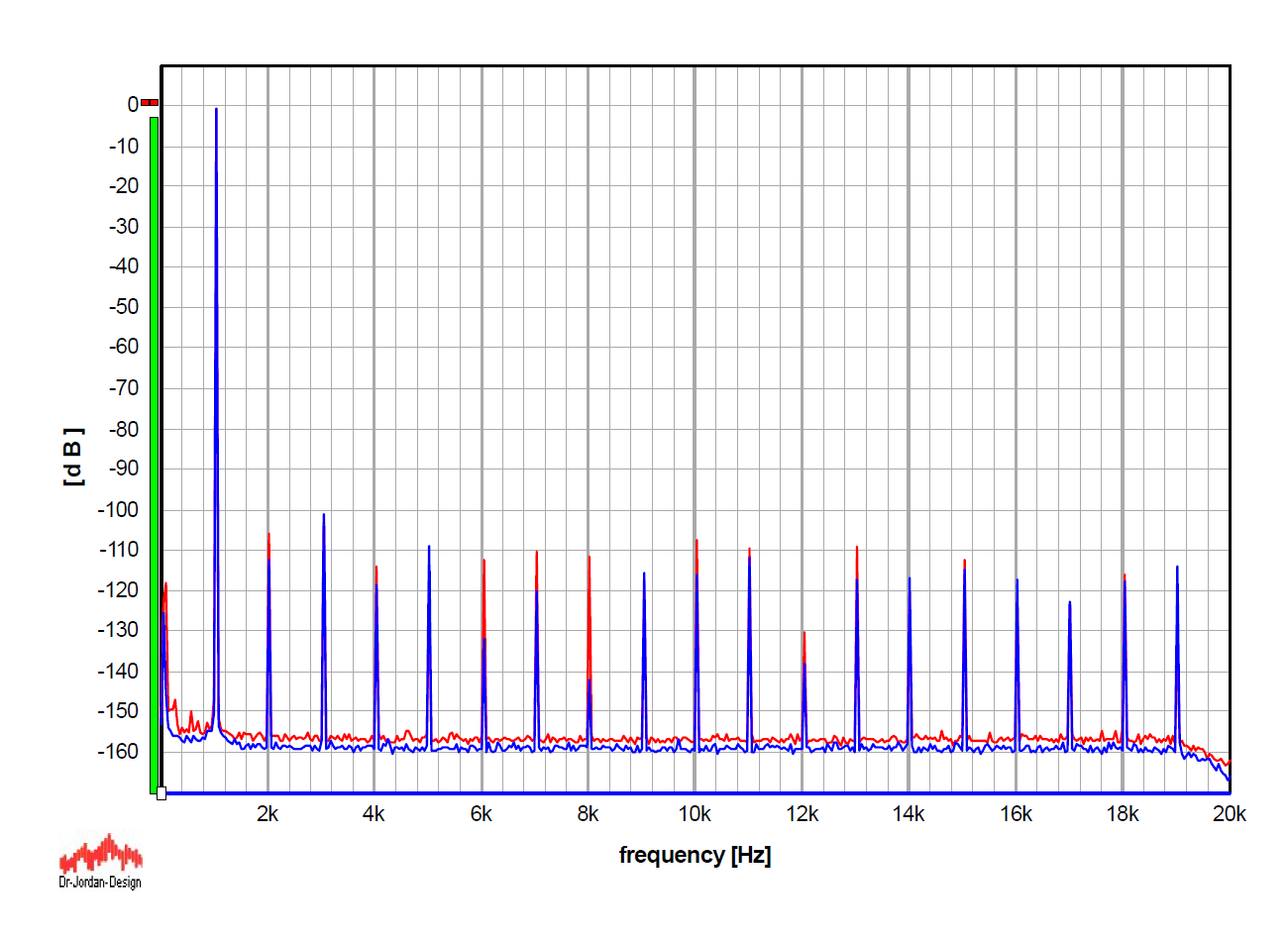
Several lower-order components are dominated by the output stage, but as everything is actually close to the limits of the DAC chips, you also see some "stubborn" higher-order components. Unlike in no-feedback analog circuits, their levels do not generally fall off with harmonic order, which indicates that they originate mainly in the converter chips rather than in the analog output stage. Also, as a side note, I may add that the graph, with the blue XLR curve on top, hides a somewhat interesting fact: the third and especially the fifth harmonic may sometimes be a few dB higher at the XLR output (something to think about later).
Both outputs show extremely low wideband noise. The visible difference in favour of XLR is probably actually larger, with about 6 dB expected here, but at -160 dB I am already at the limit of the measurement setup.
The bottom end of the audio spectrum, where the mains frequency and the dominant portion of ground-loop spurious signals also usually show up, also indicates the advantage of the XLR connection. I paid particular attention to the grounding of the measurement system, and although at my best I can achieve figures about 10 dB better for RCA and 20 dB better for XLR, both figures shown here are low (please note that -120 dB corresponds to 2.2 µV for the RCA curve and 4.4 µV for the XLR curve), several orders of magnitude below any audible threshold, and should be considered excellent as such.
With such performance, please note that the final in-system noise in this part of the spectrum becomes related more to the system power and interconnections than to the performance of the unit itself. In typical systems, I would expect the difference in noise in this bottom part of the spectrum between RCA and XLR to be greater, and more in favour of XLR.
The next and final part will deal with the sound itself.