

PC: today's grey area of hi-fi experience

Quote from Pedja on 10 October 2019, 7:37 PMToday's asynchronous USB D/A converters, with galvanic isolation from PC, were supposed to make PCs sonically invisible, provided the PC output the bit-perfect data. The things however did not turn out really like that. Even though such DACs are less critical regarding the PC qualities than the earlier generation of non-isolated adaptive USB converters was, the PCs still did not become really unimportant. Some might say, the problem has just moved to another level.
Usually, and for the good reasons, technically oriented audio devotees consider two major contributors to the digital source qualities: the one is the data quality (bit-perfection or bit-transparency), and the other is the signal quality (signal integrity). I spotted these issues some time ago in a separate article.
Indeed, by solving known problems associated with the data and signal integrity, it is possible to achieve significant sonic improvements, and cure many, or maybe even most of the traditional problems we experienced in the digital domain. Namely, by providing bit-perfect data, and feeding the D/A converter directly by the good clock, and keeping the noise inside the unit low, the digital audio is able to push its subjective sound quality way ahead of what was achieved in the old, and not that good, "perfect sound forever" days. (Notice: The analog audio parts of the D/A conversion process, such as I/V stages, are out of the scope of this topic.)
Still, some of us dealing with digital audio are aware of certain ways to change the sonic properties of the digital audio source, apparently not changing any performance mentioned above.
And this problem - and yes, this is the "problem" - is older than USB audio. For instance, back in CD days, we wanted to know why numerically identical CDs can sound different. So, before we proceed, may I recall one excellent article from the 90s, by Julian Dunn et al?
http://resources.prismsound.com/tm/cdinvest.pdf
Today's asynchronous USB D/A converters, with galvanic isolation from PC, were supposed to make PCs sonically invisible, provided the PC output the bit-perfect data. The things however did not turn out really like that. Even though such DACs are less critical regarding the PC qualities than the earlier generation of non-isolated adaptive USB converters was, the PCs still did not become really unimportant. Some might say, the problem has just moved to another level.
Usually, and for the good reasons, technically oriented audio devotees consider two major contributors to the digital source qualities: the one is the data quality (bit-perfection or bit-transparency), and the other is the signal quality (signal integrity). I spotted these issues some time ago in a separate article.
Indeed, by solving known problems associated with the data and signal integrity, it is possible to achieve significant sonic improvements, and cure many, or maybe even most of the traditional problems we experienced in the digital domain. Namely, by providing bit-perfect data, and feeding the D/A converter directly by the good clock, and keeping the noise inside the unit low, the digital audio is able to push its subjective sound quality way ahead of what was achieved in the old, and not that good, "perfect sound forever" days. (Notice: The analog audio parts of the D/A conversion process, such as I/V stages, are out of the scope of this topic.)
Still, some of us dealing with digital audio are aware of certain ways to change the sonic properties of the digital audio source, apparently not changing any performance mentioned above.
And this problem - and yes, this is the "problem" - is older than USB audio. For instance, back in CD days, we wanted to know why numerically identical CDs can sound different. So, before we proceed, may I recall one excellent article from the 90s, by Julian Dunn et al?
http://resources.prismsound.com/tm/cdinvest.pdf
Quote from Pedja on 10 October 2019, 9:21 PMNow, back to PC. How can we change its sonic properties?
We can do it both by the hardware, and by the software.
So, firstly about the hardware.
Here is the mail I got some time ago from the Model S USB customer, once he tried the USB conditioner. (Forwarded by Jim's permission.)
"It works! The noise floor is reduced, voices and instruments sound more clear and refined, and bass is more articulate.
I use a Macbook, and I think these types of units work best with non-audio (noisy) sources. I am guessing that is why there is a significant improvement in my case. With a dedicated audio music server, my guess is there would not be much of an improvement."
It was also the time I've been considering making some improvements in this domain. And, as you might be aware, the Audial USB design was slightly revised in 2017, with the second run of Audial USB interface board. In addition to previously used stand-alone (local, or self-) supply for audio clocks, it also brought a stand-alone supply for the USB decoder. Basically, this USB decoder stage is really and purely digital stage, whose output is isolated and re-clocked, so this has no effect on jitter performance or noise levels in the audio part. And that was why this stage was using supply from the USB line.However, more people were reporting success by experimenting with Vbus conditioners. And once I tried to go with local supply for this stage too, I had no problem to hear the change.
Moreover, I could easily hear the quality of the supply used here. My first and quick effort to experiment with this part was to connect my lab supply, which is the linear supply, so I set it to 5V, and hooked the USB decoder up to it, instead of the Vbus. Now, please note that the PC supplies are usually switching supplies, and switching supplies usually have good bass and dynamics, and smooth tone. As for their bad sides: they are dry, so brass instruments for instance never get lush and fresh, and you might even get tired after some time. With this lab supply, I could easily hear the change. It was more clean and I liked the resolution, but it lacked the scale in comparison to Vbus, and was too thin, up to the point of fatigue. But it was still only the lab supply. So I connected the "real thing" instead. And then there was no way back.
Now, back to PC. How can we change its sonic properties?
We can do it both by the hardware, and by the software.
So, firstly about the hardware.
Here is the mail I got some time ago from the Model S USB customer, once he tried the USB conditioner. (Forwarded by Jim's permission.)
"It works! The noise floor is reduced, voices and instruments sound more clear and refined, and bass is more articulate.
I use a Macbook, and I think these types of units work best with non-audio (noisy) sources. I am guessing that is why there is a significant improvement in my case. With a dedicated audio music server, my guess is there would not be much of an improvement."
It was also the time I've been considering making some improvements in this domain. And, as you might be aware, the Audial USB design was slightly revised in 2017, with the second run of Audial USB interface board. In addition to previously used stand-alone (local, or self-) supply for audio clocks, it also brought a stand-alone supply for the USB decoder. Basically, this USB decoder stage is really and purely digital stage, whose output is isolated and re-clocked, so this has no effect on jitter performance or noise levels in the audio part. And that was why this stage was using supply from the USB line.
However, more people were reporting success by experimenting with Vbus conditioners. And once I tried to go with local supply for this stage too, I had no problem to hear the change.
Moreover, I could easily hear the quality of the supply used here. My first and quick effort to experiment with this part was to connect my lab supply, which is the linear supply, so I set it to 5V, and hooked the USB decoder up to it, instead of the Vbus. Now, please note that the PC supplies are usually switching supplies, and switching supplies usually have good bass and dynamics, and smooth tone. As for their bad sides: they are dry, so brass instruments for instance never get lush and fresh, and you might even get tired after some time. With this lab supply, I could easily hear the change. It was more clean and I liked the resolution, but it lacked the scale in comparison to Vbus, and was too thin, up to the point of fatigue. But it was still only the lab supply. So I connected the "real thing" instead. And then there was no way back.
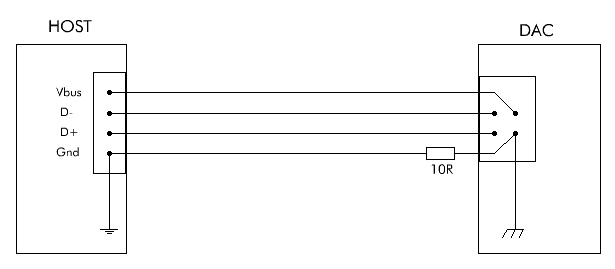
Quote from Pedja on 31 October 2019, 5:55 PMPhysically, the USB interface consists of four connections: apart from the supply provided to the peripheral device (Vbus), it has the ground connection, and differential data pair (D+, D-).
A ground may seem most closely related to the Vbus - if we suppose that, in some peculiar way, the noise gets through to the device via Vbus, we can also suppose that it gets through the ground connection too, as a common mode noise. And if this was correct, how would we deal with it?
One may think about two ways. The one is to break the ground connection completely, however there are numerous reasons (too many to mention) why the host and peripheral device, unless they are truly isolated, should share the same ground reference, so that's not what I'd recommend here.
The other is to try to force the stray ground currents to run the other ways. This can be done by inserting a small value series resistor into the ground line. The bad side is that, inserting the resistor here will violate the USB (applies to USB 2.0 and later) impedance requirements (90 Ohm differentially, expectedly set by the 45 Ohm between each data pole and the ground), of course assuming that this impedance is designed properly and is uniform at all, all along the line. But, if we do try this, what does happen, does this change the things sonically? Well, the effects might not be immediately that obvious as with the above described Vbus change, but the answer is positive: it is often quite audible.
So, to picture this:
The same can be also done before the connector, say as a part of the USB cable. Also, a ferrite bead, with its own advantages and shortcomings, may be used instead of the resistor.
Physically, the USB interface consists of four connections: apart from the supply provided to the peripheral device (Vbus), it has the ground connection, and differential data pair (D+, D-).
A ground may seem most closely related to the Vbus - if we suppose that, in some peculiar way, the noise gets through to the device via Vbus, we can also suppose that it gets through the ground connection too, as a common mode noise. And if this was correct, how would we deal with it?
One may think about two ways. The one is to break the ground connection completely, however there are numerous reasons (too many to mention) why the host and peripheral device, unless they are truly isolated, should share the same ground reference, so that's not what I'd recommend here.
The other is to try to force the stray ground currents to run the other ways. This can be done by inserting a small value series resistor into the ground line. The bad side is that, inserting the resistor here will violate the USB (applies to USB 2.0 and later) impedance requirements (90 Ohm differentially, expectedly set by the 45 Ohm between each data pole and the ground), of course assuming that this impedance is designed properly and is uniform at all, all along the line. But, if we do try this, what does happen, does this change the things sonically? Well, the effects might not be immediately that obvious as with the above described Vbus change, but the answer is positive: it is often quite audible.
So, to picture this:

The same can be also done before the connector, say as a part of the USB cable. Also, a ferrite bead, with its own advantages and shortcomings, may be used instead of the resistor.
Quote from Pedja on 19 October 2020, 5:09 PMBut, how about the USB cable shield? The USB employs differential signaling, and in such balanced connections the shield is normally not meant to work as a return or ground path, but only to shield the signal carrying conductors. Yet, it should be tied to the ground. The problem here is, it may act as a ground lead's doppelganger. And then, wouldn't it negate the effect of the above said resistor?
The cables shields are a somewhat tricky zone, and oftentimes it is not fully clear how they work and behave. Consequently, you will see different approaches to the USB cable shielding as well. Not only among the audiophiles (this is expected) - there is no consensus among the engineers either.
I believe there are several points to consider about the USB shield, to get some (hopefully) realistic picture.
First, if we want to cut the connection that makes the USB shield an alternative ground path, it is best to leave the shield unconnected at one end. In such schemes it is usually the peripheral device end, while at the source (host) device the shield should be connected to the ground, keeping it at a steady potential. (By all odds, leaving the shield completely floating is not a good idea.) That way the shield will not carry inter-chassis currents, and will not provide an alternative path for the ground loops.
But then, there is an EMI/EMC. Canonical RF engineers will tell you the above approach do not work as Faraday cage at very high frequencies (it is rather magnetic than electric field there), and recommend connecting both shield's ends, so both the host and peripheral device shield's ends, to the respective grounds (so the electric currents counteracting the magnetic field can flow). And if you are keen to limit the emission, and make the shield effective protection from the external interference, this is probably good advice.
Yet, some (minimalist approach audiophiles) do totally the opposite, and ditch the USB shield completely. I am not sure if this is what they have on their mind, but the USB connection uses differential signaling, which solves a lot of the above problems per se. And for what its worth, you may be surprised to find some USB cables not even having a shield at all. Yet, they may work fine in many applications. This is probably because the USB shield doesn't work that much to protect the conductors from external interference, but rather to stop them from radiating around.
So, where is the compromise that gets as much as possible from this game, providing reasonable shielding effectiveness, while still controlling the inter-chassis currents flow, in our usual environments?
(To be continued...)
But, how about the USB cable shield? The USB employs differential signaling, and in such balanced connections the shield is normally not meant to work as a return or ground path, but only to shield the signal carrying conductors. Yet, it should be tied to the ground. The problem here is, it may act as a ground lead's doppelganger. And then, wouldn't it negate the effect of the above said resistor?
The cables shields are a somewhat tricky zone, and oftentimes it is not fully clear how they work and behave. Consequently, you will see different approaches to the USB cable shielding as well. Not only among the audiophiles (this is expected) - there is no consensus among the engineers either.
I believe there are several points to consider about the USB shield, to get some (hopefully) realistic picture.
First, if we want to cut the connection that makes the USB shield an alternative ground path, it is best to leave the shield unconnected at one end. In such schemes it is usually the peripheral device end, while at the source (host) device the shield should be connected to the ground, keeping it at a steady potential. (By all odds, leaving the shield completely floating is not a good idea.) That way the shield will not carry inter-chassis currents, and will not provide an alternative path for the ground loops.
But then, there is an EMI/EMC. Canonical RF engineers will tell you the above approach do not work as Faraday cage at very high frequencies (it is rather magnetic than electric field there), and recommend connecting both shield's ends, so both the host and peripheral device shield's ends, to the respective grounds (so the electric currents counteracting the magnetic field can flow). And if you are keen to limit the emission, and make the shield effective protection from the external interference, this is probably good advice.
Yet, some (minimalist approach audiophiles) do totally the opposite, and ditch the USB shield completely. I am not sure if this is what they have on their mind, but the USB connection uses differential signaling, which solves a lot of the above problems per se. And for what its worth, you may be surprised to find some USB cables not even having a shield at all. Yet, they may work fine in many applications. This is probably because the USB shield doesn't work that much to protect the conductors from external interference, but rather to stop them from radiating around.
So, where is the compromise that gets as much as possible from this game, providing reasonable shielding effectiveness, while still controlling the inter-chassis currents flow, in our usual environments?
(To be continued...)
Quote from Berny on 19 October 2020, 8:10 PMNice, thank you for the update! For EMI on the datalines (probably I'm spoiling things here by jumping ahead)Â there are also common mode chokes / filters available.. but they are so tiny.
The bigger ferite you clamp over the whole cable (which you sugested in a previous post for the gnd line already) have at the same time similar results on the data lines and easier to implement (but to be honest I don't hear a difference).
You mentioned back then there would be shortcomings to the use of these... what are they?
Nice, thank you for the update! For EMI on the datalines (probably I'm spoiling things here by jumping ahead)Â there are also common mode chokes / filters available.. but they are so tiny.
The bigger ferite you clamp over the whole cable (which you sugested in a previous post for the gnd line already) have at the same time similar results on the data lines and easier to implement (but to be honest I don't hear a difference).
You mentioned back then there would be shortcomings to the use of these... what are they?
Quote from Pedja on 20 October 2020, 12:18 AMThe inductive part of the beads impedance makes them generally more effective than resistors in the HF noise filtering. But their impedance as a whole is usually not simple and makes them harder to use in a controlled way.
The inductive part of the beads impedance makes them generally more effective than resistors in the HF noise filtering. But their impedance as a whole is usually not simple and makes them harder to use in a controlled way.
Quote from Berny on 23 October 2020, 4:10 PMThank you.
I believe in most applications, for the data lines there needs to be a 22Ohm series resistor on D+ and D-. I haven't looked in detail yet on how it is implemeted on your USB MKII, but do you believe additional benefit could be gained from transforming these 2 resistors into a T-filter (or cutting the cable and inserting it there)?:
D+ --- 10Ohm--------10Ohm---
C
D- --- 10Ohm--------10Ohm---
I understand it will also slow down rise and fall times, but suppose the USB interface would not suffer from that to a certain extend... Do you have a guess of what C value would be tolerable?
At the same time, since we cut the cable anyway just before the input of our dac... we could also insert a similar full T-filter into Gnd and Vbus lines as well, keeping the unwanted RF/HF noise outside the box of our preciouse electronics. 🙂 In the end asking myself if 'T' has even any particulr benefit over regular RC and if it is the correct name.....
Hope this might have more effect than the ferite I tried...
Thank you.
I believe in most applications, for the data lines there needs to be a 22Ohm series resistor on D+ and D-. I haven't looked in detail yet on how it is implemeted on your USB MKII, but do you believe additional benefit could be gained from transforming these 2 resistors into a T-filter (or cutting the cable and inserting it there)?:
D+ --- 10Ohm--------10Ohm---
C
D- --- 10Ohm--------10Ohm---
I understand it will also slow down rise and fall times, but suppose the USB interface would not suffer from that to a certain extend... Do you have a guess of what C value would be tolerable?
At the same time, since we cut the cable anyway just before the input of our dac... we could also insert a similar full T-filter into Gnd and Vbus lines as well, keeping the unwanted RF/HF noise outside the box of our preciouse electronics. 🙂 In the end asking myself if 'T' has even any particulr benefit over regular RC and if it is the correct name.....
Hope this might have more effect than the ferite I tried...
Quote from Pedja on 25 October 2020, 12:03 AMI am not sure if low pass filtering is convenient here. A high-speed USB requires 480 MHz bandwidth, so something like 700 ps edge is the upper limit, required even for sine wave.
In this case, if I am not mistaken, the impedance seen by the cap will be 55 Ohm (110 Ohm at both sides – 90 Ohm termination per USB 2.0 specs, and 2 x 10 Ohm in series). So, a 12-13 pF will come into the required bandwidth and attenuate the signal, but even less than that will make it not look very much like a square.
Audial USB stage data inputs are connected directly to the USB PHY (physical layer) chip. (The chip itself includes 45 Ohm termination from both D+ and D- to the ground, to achieve the required 90 Ohm differential impedance.)
I am not sure if low pass filtering is convenient here. A high-speed USB requires 480 MHz bandwidth, so something like 700 ps edge is the upper limit, required even for sine wave.
In this case, if I am not mistaken, the impedance seen by the cap will be 55 Ohm (110 Ohm at both sides – 90 Ohm termination per USB 2.0 specs, and 2 x 10 Ohm in series). So, a 12-13 pF will come into the required bandwidth and attenuate the signal, but even less than that will make it not look very much like a square.
Audial USB stage data inputs are connected directly to the USB PHY (physical layer) chip. (The chip itself includes 45 Ohm termination from both D+ and D- to the ground, to achieve the required 90 Ohm differential impedance.)