


Understanding the TDA1541(A) DEM decoupling capacitors

Quote from Pedja on 22 August 2026, 7:34 PMThis old subject gets rehashed periodically, so it might be time to shed more light on what these capacitors really do and how they do it. Also, this topic is kind of a follow-up to two previous topics on TDA1541(A) DEM, so I would advise reading them, too.
AYA 5 decoupling capacitors?
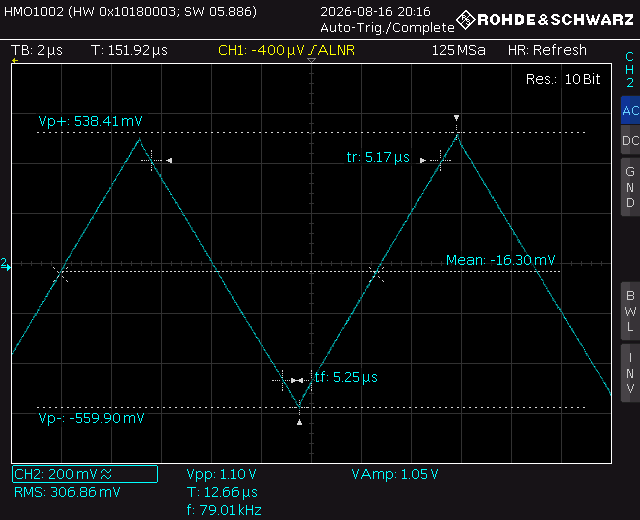
TDA1541A DEM clockingThe problem we start with, and which has to be solved with these capacitors, is shown in the waveform shots I've taken at all the unfiltered DEM pins of one TDA1541A chip. Also, since the idea was not only to show these waveforms, but also how they break through to the DAC output, and since the audio measurement setup I normally use is (software) limited to Fs=192 kHz, I used 1 nF at the Cosc pins, which sets the TDA1541A DEM frequency to 75-80 kHz, so the findings are representative within the associated 96 kHz (Fs/2) bandwidth. Hence, first, the waveform between the Cosc pins.
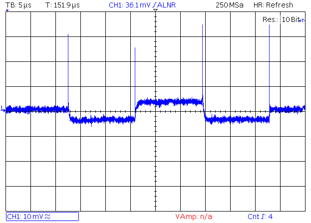
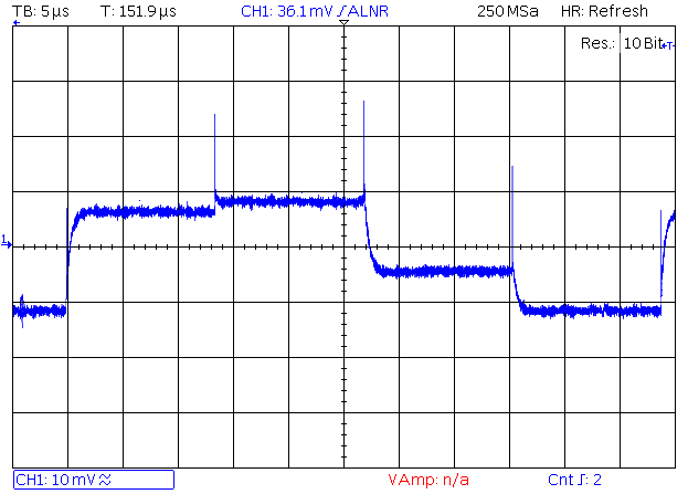
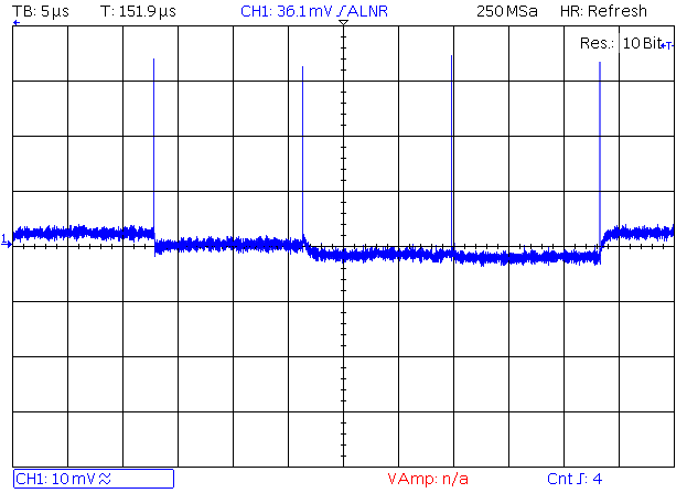
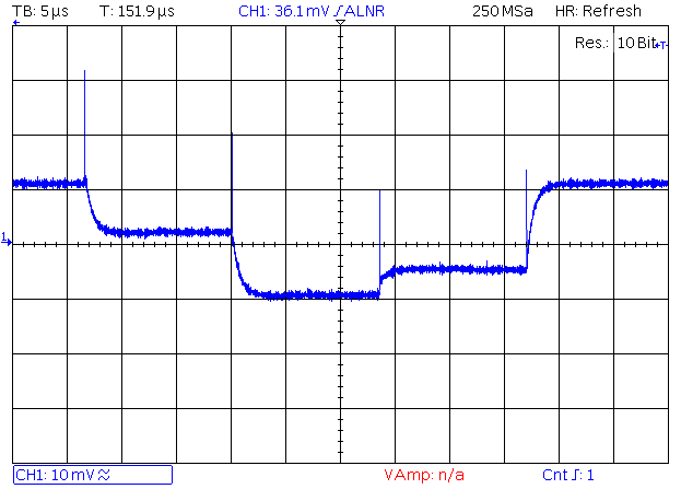
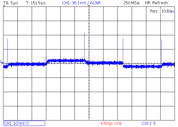
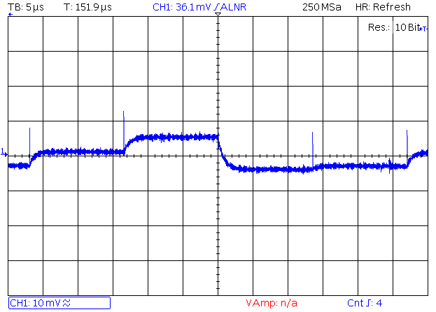
So, I ditched the DEM decoupling capacitors and captured the spurious signals at the unfiltered DEM pins. The TDA1541A chip used here is the series HSH9314. You will note that the spurious signals vary considerably between the different pins. In the order shown below, the pins are MSB, MSB-1, MSB-2, MSB-3, MSB-4, MSB-5, and MSB-6.
This old subject gets rehashed periodically, so it might be time to shed more light on what these capacitors really do and how they do it. Also, this topic is kind of a follow-up to two previous topics on TDA1541(A) DEM, so I would advise reading them, too.
AYA 5 decoupling capacitors?
TDA1541A DEM clocking
The problem we start with, and which has to be solved with these capacitors, is shown in the waveform shots I've taken at all the unfiltered DEM pins of one TDA1541A chip. Also, since the idea was not only to show these waveforms, but also how they break through to the DAC output, and since the audio measurement setup I normally use is (software) limited to Fs=192 kHz, I used 1 nF at the Cosc pins, which sets the TDA1541A DEM frequency to 75-80 kHz, so the findings are representative within the associated 96 kHz (Fs/2) bandwidth. Hence, first, the waveform between the Cosc pins.
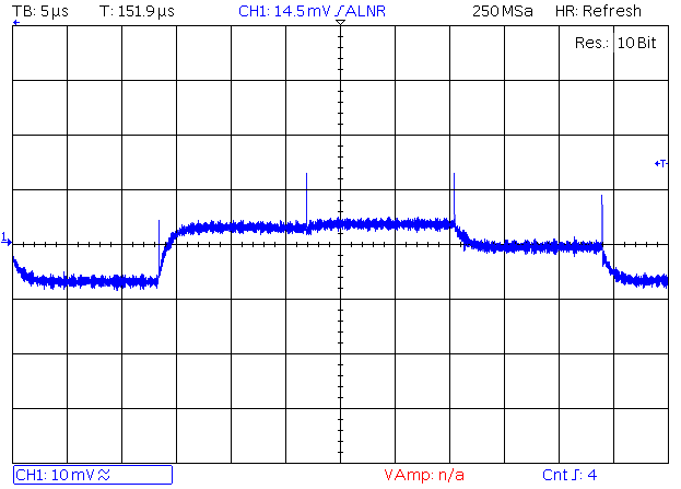
So, I ditched the DEM decoupling capacitors and captured the spurious signals at the unfiltered DEM pins. The TDA1541A chip used here is the series HSH9314. You will note that the spurious signals vary considerably between the different pins. In the order shown below, the pins are MSB, MSB-1, MSB-2, MSB-3, MSB-4, MSB-5, and MSB-6.
Quote from Pedja on 24 August 2026, 1:13 PMSo, how do these spurious signals add up and make their way through to the audio output?
The spectral analysis of the idle output shows four frequencies associated with the DEM frequency: its 1/4 (18.7 kHz), 1/2 (37.4 kHz), 3/4 (56 kHz), and the DEM frequency itself (74.8 kHz). An additional component at 93.5 kHz also indicates the presence of higher-order components, but their levels appear to be decreasing. Other than DEM-related frequencies, you will also see 44.1 kHz at about -117 dBFS, related to the sampling frequency, which can be ignored here.
The 0 dBFS level on the graph matches the DAC's full-scale 2.2 V RMS output, so a dominant F(DEM)/2 peak at -70 dBFS equals about 0.7 mV RMS, or 2 mV peak-to-peak.
Now, how did all those spurious waveforms at the DEM pins add up at the DAC audio output? The complete story might be too long to tell here, so to cut it short: the spurious DEM signals are "weighted", so the spurs from the MSB pin dominate.
This is also partly visible from the figures above. If you look at the spurious signal waveform at MSB pin, you will see that it is the only pin whose spurious signal's basic frequency is mostly F(DEM)/2 (it consecutively toggles up and down), while at all the other pins it is apparently the F(DEM)/4 – yet, the F(DEM)/2 level at the DAC output is the highest.
It might also be interesting to mention that, with one of the other TDA1541A samples I checked during these tests, the spurious signal at the unfiltered MSB DEM pin was below the intrinsic noise level of this oscilloscope/probe setup, and the resulting spurious level at the audio output was below -100 dBFS. This is, however, not something one should normally expect or count on.
Now, what is the rejection between the DEM pins and the DAC output? Putting the high-frequency spikes aside for now, the bulk of the remaining MSB pin waveform is about 7 mV peak-to-peak. Taking into account that the MSB contributes half (-6 dB) of the full DAC output level, the conclusion, if I am right, is that the rejection between this MSB DEM pin and the DAC output in this sub-100 kHz area is barely about 5 dB.
In other words, nothing to rely on. Or, in more practical terms, the DEM decoupling capacitors act just about as the (shunt) capacitors in the audio signal path itself. So, they are not "out there", in the (dark) digital domain, and must be chosen with their audio performance in mind.
As for the other phenomena visible here, we can also note that the DEM oscillators' frequency drifts noticeably over time, which is expected for an astable multivibrator. You will note it shifted down from about 79 kHz at power-up when I took the DEM clock waveform shot, to about 75 kHz an hour later when I measured the DAC output.
Also, the levels of the DEM spurious signals fluctuate too, by several decibels, as you would also expect from any real-world current sources.
Normally, the spurious waveforms and levels differ somewhat between different TDA samples and series, and there is no rule regarding the bits at which the ripple is highest or lowest. But this does not actually change much either about things investigated in this article, or about the general TDA1541(A) performance.
And finally, the skirts you see around the DEM-related frequencies are not measurement artifacts. The measurement setup is very low jitter, and the FFT size was set to 512 k, with ADC Fs=192 kHz yielding about 0.37 Hz bin resolution. The skirts you see are indeed the jitter modulation of the DEM oscillator, and this is again expected for an astable multivibrator. The jitter of this DEM oscillator, however, has absolutely nothing to do with the DAC sampling (audio) jitter.
So, now with the problem hopefully well characterized, the next part will be about the work of the DEM decoupling capacitors.
So, how do these spurious signals add up and make their way through to the audio output?
The spectral analysis of the idle output shows four frequencies associated with the DEM frequency: its 1/4 (18.7 kHz), 1/2 (37.4 kHz), 3/4 (56 kHz), and the DEM frequency itself (74.8 kHz). An additional component at 93.5 kHz also indicates the presence of higher-order components, but their levels appear to be decreasing. Other than DEM-related frequencies, you will also see 44.1 kHz at about -117 dBFS, related to the sampling frequency, which can be ignored here.
The 0 dBFS level on the graph matches the DAC's full-scale 2.2 V RMS output, so a dominant F(DEM)/2 peak at -70 dBFS equals about 0.7 mV RMS, or 2 mV peak-to-peak.

Now, how did all those spurious waveforms at the DEM pins add up at the DAC audio output? The complete story might be too long to tell here, so to cut it short: the spurious DEM signals are "weighted", so the spurs from the MSB pin dominate.
This is also partly visible from the figures above. If you look at the spurious signal waveform at MSB pin, you will see that it is the only pin whose spurious signal's basic frequency is mostly F(DEM)/2 (it consecutively toggles up and down), while at all the other pins it is apparently the F(DEM)/4 – yet, the F(DEM)/2 level at the DAC output is the highest.
It might also be interesting to mention that, with one of the other TDA1541A samples I checked during these tests, the spurious signal at the unfiltered MSB DEM pin was below the intrinsic noise level of this oscilloscope/probe setup, and the resulting spurious level at the audio output was below -100 dBFS. This is, however, not something one should normally expect or count on.
Now, what is the rejection between the DEM pins and the DAC output? Putting the high-frequency spikes aside for now, the bulk of the remaining MSB pin waveform is about 7 mV peak-to-peak. Taking into account that the MSB contributes half (-6 dB) of the full DAC output level, the conclusion, if I am right, is that the rejection between this MSB DEM pin and the DAC output in this sub-100 kHz area is barely about 5 dB.
In other words, nothing to rely on. Or, in more practical terms, the DEM decoupling capacitors act just about as the (shunt) capacitors in the audio signal path itself. So, they are not "out there", in the (dark) digital domain, and must be chosen with their audio performance in mind.
As for the other phenomena visible here, we can also note that the DEM oscillators' frequency drifts noticeably over time, which is expected for an astable multivibrator. You will note it shifted down from about 79 kHz at power-up when I took the DEM clock waveform shot, to about 75 kHz an hour later when I measured the DAC output.
Also, the levels of the DEM spurious signals fluctuate too, by several decibels, as you would also expect from any real-world current sources.
Normally, the spurious waveforms and levels differ somewhat between different TDA samples and series, and there is no rule regarding the bits at which the ripple is highest or lowest. But this does not actually change much either about things investigated in this article, or about the general TDA1541(A) performance.
And finally, the skirts you see around the DEM-related frequencies are not measurement artifacts. The measurement setup is very low jitter, and the FFT size was set to 512 k, with ADC Fs=192 kHz yielding about 0.37 Hz bin resolution. The skirts you see are indeed the jitter modulation of the DEM oscillator, and this is again expected for an astable multivibrator. The jitter of this DEM oscillator, however, has absolutely nothing to do with the DAC sampling (audio) jitter.
So, now with the problem hopefully well characterized, the next part will be about the work of the DEM decoupling capacitors.
Quote from Pedja on 27 August 2026, 10:18 AMAnd here is what we get with 100 nF capacitors installed, and how they attenuate DEM-related components. It is not of primary interest here, but the drop in the noise floor is visible, too.
The attenuation achieved by these capacitors within this range is defined by the ratio between the DAC internal DEM circuit impedance at this point, which in practice can be anything between 1-2 and 7-8 kOhm, and the capacitor's impedance. For 100 nF capacitance, at the roughly 38 kHz frequency dominating here, this is somewhat above 40 Ohm. Consequently, at 19 kHz it is about 84 Ohm, at 56 kHz about 28 Ohm, etc. So, the attenuation of these capacitors, at the given frequency, in dB, is 20*log[Z(DEM)/Z(cap)], and all this works out to somewhere between 30 and 45 dB. Or, in terms of voltage, 100 times or 40 dB means that, for instance, 10 mV will be attenuated to 100 µV.
Also, please note that, in more typical cases, with the DEM frequency set to 160-200 kHz, the same 100 nF capacitors, practically speaking, achieve 6-8 dB better attenuation than what you see in this graph. So, both F(DEM)/4 and F(DEM)/2 components, which then come at 40-50 kHz and 80-100 kHz, fall to about -110 dBFS.
Yet, obviously, using a higher capacitance would bring more attenuation in this range. However, higher-capacitance capacitors usually also have higher parasitic inductance (ESL), which compromises high-frequency spike filtering. And the TDA1541(A) DEM high-frequency switching spikes, with their rise and fall times of 20-30 ns, mean that we must also consider the 30-50 MHz region in the frequency domain. And while the attenuation in the sub-100 kHz range is practically solely defined by the capacitance value, the attenuation at 30-50 MHz is associated with the capacitors' parasitic inductance and the layout.
So, what about those high-frequency spikes? How do we check the way these spikes disturb the conversion? Of course, we can see on the scope, within its resolution, how these spikes are attenuated at the DEM pins (please refer to the topic AYA 5 decoupling capacitors?), but we cannot normally see 30 MHz or 50 MHz frequencies breaking through to the DAC output – they are simply out of its regular bandwidth. Also, such problems usually do not show up as conventional harmonic or intermodulation distortion. Yet, they do affect the overall subjective audio performance, and it is a fundamental rule to keep such HF spurs away from the conversion process.
And my next post will be about the high-frequency part of this problem, mostly addressing the capacitors themselves.
And here is what we get with 100 nF capacitors installed, and how they attenuate DEM-related components. It is not of primary interest here, but the drop in the noise floor is visible, too.

The attenuation achieved by these capacitors within this range is defined by the ratio between the DAC internal DEM circuit impedance at this point, which in practice can be anything between 1-2 and 7-8 kOhm, and the capacitor's impedance. For 100 nF capacitance, at the roughly 38 kHz frequency dominating here, this is somewhat above 40 Ohm. Consequently, at 19 kHz it is about 84 Ohm, at 56 kHz about 28 Ohm, etc. So, the attenuation of these capacitors, at the given frequency, in dB, is 20*log[Z(DEM)/Z(cap)], and all this works out to somewhere between 30 and 45 dB. Or, in terms of voltage, 100 times or 40 dB means that, for instance, 10 mV will be attenuated to 100 µV.
Also, please note that, in more typical cases, with the DEM frequency set to 160-200 kHz, the same 100 nF capacitors, practically speaking, achieve 6-8 dB better attenuation than what you see in this graph. So, both F(DEM)/4 and F(DEM)/2 components, which then come at 40-50 kHz and 80-100 kHz, fall to about -110 dBFS.
Yet, obviously, using a higher capacitance would bring more attenuation in this range. However, higher-capacitance capacitors usually also have higher parasitic inductance (ESL), which compromises high-frequency spike filtering. And the TDA1541(A) DEM high-frequency switching spikes, with their rise and fall times of 20-30 ns, mean that we must also consider the 30-50 MHz region in the frequency domain. And while the attenuation in the sub-100 kHz range is practically solely defined by the capacitance value, the attenuation at 30-50 MHz is associated with the capacitors' parasitic inductance and the layout.
So, what about those high-frequency spikes? How do we check the way these spikes disturb the conversion? Of course, we can see on the scope, within its resolution, how these spikes are attenuated at the DEM pins (please refer to the topic AYA 5 decoupling capacitors?), but we cannot normally see 30 MHz or 50 MHz frequencies breaking through to the DAC output – they are simply out of its regular bandwidth. Also, such problems usually do not show up as conventional harmonic or intermodulation distortion. Yet, they do affect the overall subjective audio performance, and it is a fundamental rule to keep such HF spurs away from the conversion process.
And my next post will be about the high-frequency part of this problem, mostly addressing the capacitors themselves.
Quote from Pedja on 28 August 2026, 2:11 PMSo, since capacitor impedance at 30-50 MHz is mostly defined by parasitic inductance (ESL), I modeled the impedance of some 100 nF capacitors, including their typical ESL values. I modeled several different dielectrics and packages, and also tried to point out that thicker SMD bodies, all else being equal, yield lower inductance. In reality, a large part of capacitor ESL is determined not by the dielectric, but by geometry and package.
Still, once you consider that the PCB traces or wires imply roughly 1 nH per millimeter of length, you will easily see one of the reasons why layout matters, and how, at these frequencies, several millimeters of PCB trace can have more inductance than any of these capacitors, and swamp the differences between the capacitors themselves. Of course, the use of the ground plane can significantly reduce this PCB inductance.
The ESL values I show here were mostly supplied by the manufacturers or derived from their impedance graphs. For those interested in actual parts, the ones I mostly considered were Murata GRM, Rubycon MU, Panasonic ECHU, Kyocera CB, and WIMA MKP2 and MKP4.
I used a simple one-C, one-L model for the impedance. That said, real capacitors can show more complex reactive behaviour, especially above 50-100 MHz, and I also did not include ESR as a minimal impedance value at the resonant point, but such a model is quite adequate for our purpose here.
I hope this provides enough information to draw your own conclusions, but a few additional remarks of my own are in order, too.
So, since capacitor impedance at 30-50 MHz is mostly defined by parasitic inductance (ESL), I modeled the impedance of some 100 nF capacitors, including their typical ESL values. I modeled several different dielectrics and packages, and also tried to point out that thicker SMD bodies, all else being equal, yield lower inductance. In reality, a large part of capacitor ESL is determined not by the dielectric, but by geometry and package.
Still, once you consider that the PCB traces or wires imply roughly 1 nH per millimeter of length, you will easily see one of the reasons why layout matters, and how, at these frequencies, several millimeters of PCB trace can have more inductance than any of these capacitors, and swamp the differences between the capacitors themselves. Of course, the use of the ground plane can significantly reduce this PCB inductance.
The ESL values I show here were mostly supplied by the manufacturers or derived from their impedance graphs. For those interested in actual parts, the ones I mostly considered were Murata GRM, Rubycon MU, Panasonic ECHU, Kyocera CB, and WIMA MKP2 and MKP4.
I used a simple one-C, one-L model for the impedance. That said, real capacitors can show more complex reactive behaviour, especially above 50-100 MHz, and I also did not include ESR as a minimal impedance value at the resonant point, but such a model is quite adequate for our purpose here.

I hope this provides enough information to draw your own conclusions, but a few additional remarks of my own are in order, too.
Quote from Pedja on 30 August 2026, 1:55 PMSo, at 50 MHz, each nH implies about 0.3 Ohm of reactance. Yet, other than coming from the capacitors themselves, such inductance, and hence HF impedance, also comes significantly from PCB traces and component leads.
To put this into a more realistic perspective, the inductance of chip pins like those used by the TDA1541(A) is normally about 1.3 nH for their above-PCB portion. I considered here a 0.8 mm horizontal and 2.5 mm vertical part, with a cross section of about 1.5 x 0.28 mm, and a 0.5 mm bottom part narrowing from 1.5 to 0.8 mm. Due to the bending and the quite low length-to-width ratio, their inductance is actually a few times lower than that of ordinary wires.
Appropriate chip socket pins can add anything between 1 nH and 2.5 nH. So, putting aside what happens inside the chip itself, the total inductance in the path before the signal even reaches the PCB is already higher than the ESL of any SMD capacitor appropriate for use here, including the rather humble polyester (!). If the signal must go to the bottom PCB side, a 0.7 mm via in a 1.6 mm thick PCB will add one more nH.
Further down the road, taking into account the whole return path to the TDA1541(A) analogue ground pin, and even assuming widened traces and the use of a ground plane, an overall figure of 7-8 nH is already hard to achieve, let alone to go below. So, the layout inductance is at least in the same range as that of conventional through-hole film capacitors.
In other words, the overall parasitic inductance at the DEM decoupling capacitors is determined far more by the layout than by the capacitors' own ESL.
Still, these things are not as bad as they may look. Taking the DEM impedance at this point — let's be cautious and assume something like 2-3 kOhm — and an overall inductance of 7-10 nH, which at 50 MHz equals about 2-3 Ohm of reactance, we get an attenuation of roughly 1000 times (60 dB). HF spike levels of 10 and 30 mV are thus attenuated to 10 and 30 µV.
So, as a bottom line for all these posts, for DEM decoupling I choose capacitors that fulfill these criteria, in this order of priority:
- Subjective audio performance
- HF performance
- Capacitance that does not compromise HF performance
And I settled on 100 nF SMD 1210 PPS capacitors a long time ago. I would gladly use something better here, but I am still not aware of anything like that.
So, at 50 MHz, each nH implies about 0.3 Ohm of reactance. Yet, other than coming from the capacitors themselves, such inductance, and hence HF impedance, also comes significantly from PCB traces and component leads.
To put this into a more realistic perspective, the inductance of chip pins like those used by the TDA1541(A) is normally about 1.3 nH for their above-PCB portion. I considered here a 0.8 mm horizontal and 2.5 mm vertical part, with a cross section of about 1.5 x 0.28 mm, and a 0.5 mm bottom part narrowing from 1.5 to 0.8 mm. Due to the bending and the quite low length-to-width ratio, their inductance is actually a few times lower than that of ordinary wires.
Appropriate chip socket pins can add anything between 1 nH and 2.5 nH. So, putting aside what happens inside the chip itself, the total inductance in the path before the signal even reaches the PCB is already higher than the ESL of any SMD capacitor appropriate for use here, including the rather humble polyester (!). If the signal must go to the bottom PCB side, a 0.7 mm via in a 1.6 mm thick PCB will add one more nH.
Further down the road, taking into account the whole return path to the TDA1541(A) analogue ground pin, and even assuming widened traces and the use of a ground plane, an overall figure of 7-8 nH is already hard to achieve, let alone to go below. So, the layout inductance is at least in the same range as that of conventional through-hole film capacitors.
In other words, the overall parasitic inductance at the DEM decoupling capacitors is determined far more by the layout than by the capacitors' own ESL.
Still, these things are not as bad as they may look. Taking the DEM impedance at this point — let's be cautious and assume something like 2-3 kOhm — and an overall inductance of 7-10 nH, which at 50 MHz equals about 2-3 Ohm of reactance, we get an attenuation of roughly 1000 times (60 dB). HF spike levels of 10 and 30 mV are thus attenuated to 10 and 30 µV.
So, as a bottom line for all these posts, for DEM decoupling I choose capacitors that fulfill these criteria, in this order of priority:
- Subjective audio performance
- HF performance
- Capacitance that does not compromise HF performance
And I settled on 100 nF SMD 1210 PPS capacitors a long time ago. I would gladly use something better here, but I am still not aware of anything like that.

Quote from jaffrie on 4 October 2026, 9:04 AMHi Pedja,
Very good details, kudos . Question if I may, what if I change the 470pf cap to say 560pf & for MSB 1 & 2 using staggered 0.47 uf & 0.33uf cap,
would there be any benefit in SQ. Re smd caps Im aware that Rubycon have some in this value although they arent PPS
As always many thks
Hi Pedja,
Very good details, kudos . Question if I may, what if I change the 470pf cap to say 560pf & for MSB 1 & 2 using staggered 0.47 uf & 0.33uf cap,
would there be any benefit in SQ. Re smd caps Im aware that Rubycon have some in this value although they arent PPS
As always many thks
Quote from Pedja on 4 October 2026, 8:38 PMYou are welcome, Jaffrie.
Using 560 pF instead of 470 pF at the Cosc pins decreases the DEM frequency by about 16%. For me, it is not much of a concern or a benefit, either.
Philips provided an equation relating the DEM frequency to Cosc and, empirically speaking, and as the graphs above show, this equation isn't completely accurate, but it is useful. The inaccuracy probably comes from the 1.8 kΩ internal resistance, which is claimed to vary by up to +/-25%.
F = 1 / (5.9 x 1.8 kΩ x Cosc)
As said above, the ripple from the MSB pin is most visible at the output, and this is why using a higher filtering capacitance here may make some sense. If you can stack/piggyback two SMD caps, it may be worth a try.
Rubycon makes the PMLCAP (Polymer Multi-Layer Capacitor) series MU, which are acrylic SMD capacitors. I did not try these, but I did try Cornell Dubilier acrylic, and in critical digital decoupling they may produce a smoother sound than C0G. Cornell Dubilier acrylic is now obsolete, but Rubycon might be a good replacement, or even better. On paper, their specs are exceptional (you can see that I included them in the graph above). I would still be more cautious about using them in (or around) the audio path, though.
Recently, I have seen that Rubycon is also adding the MF and MS series to its PMLCAP range, and it looks like they will use some new acrylic polymer technology. However, there is not enough information about them yet, and it is not really clear whether they bring miniaturization or performance improvements (or both). They are still not actually available either, so we will have to be patient.
You are welcome, Jaffrie.
Using 560 pF instead of 470 pF at the Cosc pins decreases the DEM frequency by about 16%. For me, it is not much of a concern or a benefit, either.
Philips provided an equation relating the DEM frequency to Cosc and, empirically speaking, and as the graphs above show, this equation isn't completely accurate, but it is useful. The inaccuracy probably comes from the 1.8 kΩ internal resistance, which is claimed to vary by up to +/-25%.
F = 1 / (5.9 x 1.8 kΩ x Cosc)
As said above, the ripple from the MSB pin is most visible at the output, and this is why using a higher filtering capacitance here may make some sense. If you can stack/piggyback two SMD caps, it may be worth a try.
Rubycon makes the PMLCAP (Polymer Multi-Layer Capacitor) series MU, which are acrylic SMD capacitors. I did not try these, but I did try Cornell Dubilier acrylic, and in critical digital decoupling they may produce a smoother sound than C0G. Cornell Dubilier acrylic is now obsolete, but Rubycon might be a good replacement, or even better. On paper, their specs are exceptional (you can see that I included them in the graph above). I would still be more cautious about using them in (or around) the audio path, though.
Recently, I have seen that Rubycon is also adding the MF and MS series to its PMLCAP range, and it looks like they will use some new acrylic polymer technology. However, there is not enough information about them yet, and it is not really clear whether they bring miniaturization or performance improvements (or both). They are still not actually available either, so we will have to be patient.
Quote from Pedja on 6 October 2026, 6:30 PMPanasonic ECHU PPS 1210 is limited to 100 nF, and I am not sure that a total of 200 nF justifies such soldering.
As a more reasonable effort, I would rather try going to 1 µF or so — of course, without compromising either audio or HF performance.
Either way, such soldering must be done carefully. As you may already know, PPS capacitors are not very soldering-friendly, and please note that acrylic capacitors are no easier to solder either.
Panasonic ECHU PPS 1210 is limited to 100 nF, and I am not sure that a total of 200 nF justifies such soldering.
As a more reasonable effort, I would rather try going to 1 µF or so — of course, without compromising either audio or HF performance.
Either way, such soldering must be done carefully. As you may already know, PPS capacitors are not very soldering-friendly, and please note that acrylic capacitors are no easier to solder either.
Quote from jaffrie on 7 October 2026, 2:57 PMThanks again Pedja, yes I've read somewhere that these pps caps dont take to heat well so not even sure that we've even damaged them during soldering lol. 1uf for both Msb or Msb one 1uf Msb two 0.47uf. Will go hunt for smd caps of this value to try.
Many thks again
Thanks again Pedja, yes I've read somewhere that these pps caps dont take to heat well so not even sure that we've even damaged them during soldering lol. 1uf for both Msb or Msb one 1uf Msb two 0.47uf. Will go hunt for smd caps of this value to try.
Many thks again